This circuit is a universal frequency generator, you can use it for many frequency and time period testing applications, so it is quite flexible. It is mainly suited for gate pulse generator use in frequency counters, that is where it fits best.
The circuit can generate a full range of reference frequencies like 1 Hz, 5 Hz, 10 Hz, 50 Hz, 100 Hz, 500 Hz, 1 kHz, 5 kHz, 10 kHz, 50 kHz, 100 kHz, 500 kHz, 1 MHz, so you have many options to work with.
At the center of the design there is a 1 MHz crystal oscillator, built using a couple of NAND gates, this part drives the whole circuit.
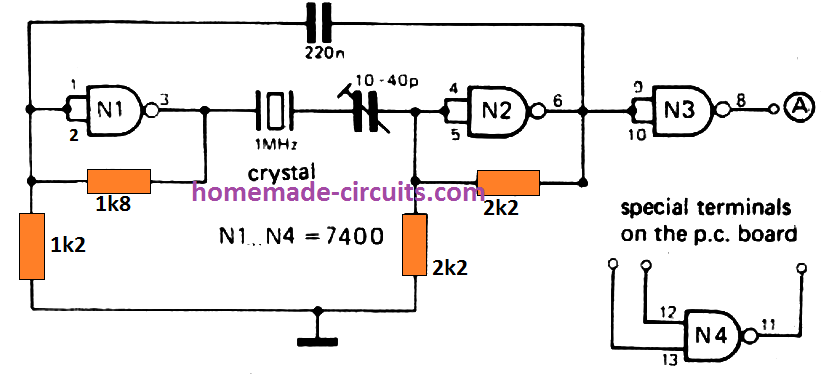
A 3rd NAND gate acts like a buffer at the output of this oscillator output of this oscillator, dividing down by a number of 7490 decade counters.
These incorporate a divide-by-2 stage accompanied by a divide-by-5 stage, that suggests that along with dividing the reference frequency down to 1 Hz in decades, signals of 500 kHz and lower values up to 5 Hz are likewise obtainable.
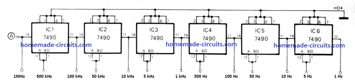
All these signals are useful mainly where gate pulses are needed for counting frequency. So for example, the 5 Hz output gives positive pulses of 100 ms width and when a 10 MHz signal is tested then, a gate pulse of this length allows 11500,000 cycles of the signal to pass to the counter, giving a display of 10,00000.
Alternatively, for time calculations, the 1 Hz to 1 MHz outputs are more useful. For example, while computing a single second interval, 1,000,000 cycles of the 1 MHz output can be measured, and then the display shows 10001300.
PCB Design
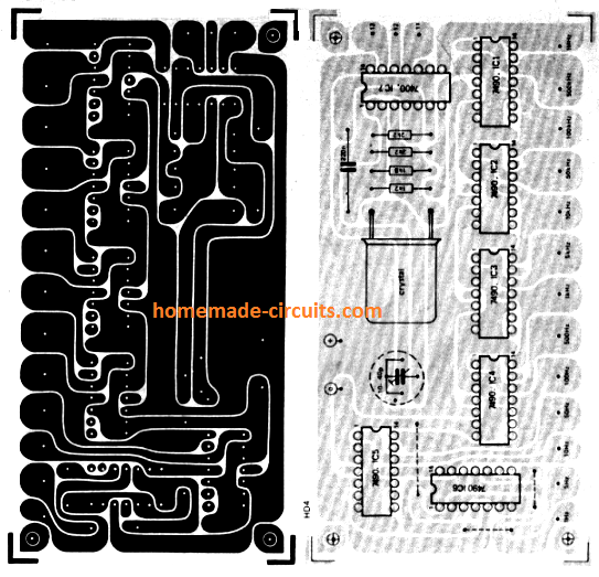
PCB design and structure is very stream-lined and presented properly. Board layout looks clean, effective. Outputs are taken from lower edge of the board diagram, so easy access there.
There is one extra NAND-gate in the bundle meant for oscillator, but this can be used as gate for frequency counter applications, so it does not go waste.
Wiring contacts for this are brought at the top right corner of the board. Oscillator frequency can be tweaked to exactly 1 MHz using the trimmer capacitor, so adjustment is possible.
Ideal way to do this is using oscilloscope, checking 100 kHz output along with 200 kHz Droitwich reception, then applying Lissajous figure. Trimmer must be fine-tuned slowly until Lissajous number stops rotating, then it is set.
Precision Crystal Controlled Time Base Circuit
This precision crystal controlled time base circuit is built using common easily available CMOS ICs and an inexpensive crystal. It gives user the option to get 50 Hz, 100 Hz or 200 Hz, you can choose.
50 Hz reference frequency can be used as time base for calibrating electronic clocks, frequency meters and many other things, so that is the main use.
IC1 is made up of an oscillator and a 20 divider, that is how the base timing is generated.
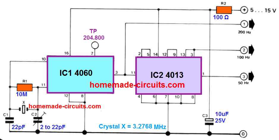
Output Frequency Working
Assuming oscillator loop is calibrated properly through C2, output at pin 3 (Q14) generates 200 Hz square wave. Now using two flip-flops from IC2, the square wave voltage is divided by 2, then again by 4, so this gives two more outputs, one at 100 Hz and one at 50 Hz
How To Calibrate
The 50 Hz is generated from pin 1. Hobbyists having frequency meter can calibrate this crystal controlled time base generator circuit easily, just hook the meter to pin 7 of IC1 (Q4), then fine-tune C2 until meter shows 204.800 Hz
As curiosity point, any user not having frequency meter should not lose heart, because adjusting trimmer C2 around center point may be enough, so you still get adequate precision for most applications
Using The 100 Hz Output
The 100 Hz output is useful for designing digital counters. For this application, we recommend attaching a 1 : 10 divider IC, like IC 4518, to the 100 Hz output pin
Power supply specifications are between 5 .. . 15 V, and current consumption is around 0.5… 2.5 mA
Leave a Reply