• Skip to main content
  • Skip to primary sidebar

Making Easy Circuits

Learn and build electronic circuits

You are here: Home / Audio and Amplifier / 1 Watt Amplifier Circuit

1 Watt Amplifier Circuit

Last Updated on November 16, 2024 by Admin Leave a Comment

The majority of the Hi Fi amplifiers being used derived from circuitry such as this layout, even though they tend to be more modern.

The 1 watt amplifier circuit utilizes a 'complementary' output stage, along with one NPN and one PNP power transistor, which often gets rid of the importance of an output transformer located in old amplifier models.

fig1 25

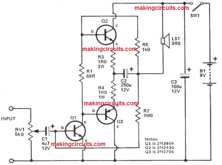
Output power is near to 1W, with realistically lower distortion. The input signal is that passes the volume control RV1 after which through C1 to the base of Q1.

The collector load for Q1 consists of R1, R5 and also the loudspeaker and the voltage at the collector will probably be around half the supply voltage, i.e. 4V5.

The bases of Q2 and Q3 can also be additionally to voltage (quite close to) since the collector of Q1 since the value of R1 is really low (68R).

At the junction of the emitters of Q2 and Q3 the voltage may also be quite close to 4V5, R3 and R4 and really low value resistors to restrict the current via Q2 and Q3.

Once the amplified input signal is no more than 4V5, Q2 is switched off (since the base will probably be at a lower voltage compared to its emitter), however Q3 will certainly perform the signal.

When Q1 amplifies the signal to over 4V5 the change occurs, Q2 performs and Q3 is switched off. The signals are merged at the the normal emitter junction of Q2 and Q3 and passed to the loudspeaker with the significant electrolytic capacitor C2.

Small values of C2 end up within a bad lower frequency result. Negative feedback is supplied by R5 and R2, all these make sure that firmness by decreasing the gain marginally.

In this 1 watt amplifier circuit R1 is incorporated to present quite a few base bias for Q2 and Q3; more modern layouts employ thermistors or diodes to stop thermal runaway' which could eliminate the output pair.

A drawback may be the DC coupling of the transistors, if one transistor alters its features the outcome could be devastating!

Because of this, the output pair can be quite a 'matched pair', other forms could be attempted provided that will not have the "matched pair"

You'll also like:

  • 1.  Simple Bird Sound Generator Circuit
  • 2.  How to Make a Cellphone RF Triggered Car Amplifier Auto-Mute Circuit
  • 3.  2 Simple Electronic Gong Circuits Explained
  • 4.  Simple Stereo Simulator Circuits
  • 5.  How to make a Extended Telephone Ring Amplifier/Repeater Circuit
  • 6.  Simple 300 Watt Power Amplifier Circuit using Transistors

About Admin

Hey friends, Thanks a bunch for stopping by this site! I am an engineer with a Bachelor of Engineering in Electronics and Telecommunication. One of my passions is gathering information from all sorts of electronics books and tutorials. I then take that information and compile it into a language that is super easy to understand. My goal is to make those complex electronics circuit concepts and technical terms much more accessible for all the new and budding electronics engineers out there. I can also design customized circuit diagrams as required by the users.
If you have any questions related to this field, please do not hesitate to drop a comment! I am always here and ready to help you out with any queries you might have. I cannot wait to hear from you!

Reader Interactions

Leave a Reply Cancel reply

Your email address will not be published. Required fields are marked *

Primary Sidebar

Categories

  • 3 Phase (4)
  • 8051 Microcontroller (1)
  • Arduino (11)
  • Audio and Amplifier (102)
  • Automation (8)
  • Battery Chargers (64)
  • Bicycle Projects (4)
  • Car and Motorcycle Projects (39)
  • Datasheets (10)
  • DIY Projects (5)
  • Electrical (15)
  • Free Energy (6)
  • Games Projects (2)
  • High Voltage (14)
  • Hobby Projects (30)
  • Household Circuits (2)
  • IC 555 Circuits (5)
  • Ignition Circuits (2)
  • Indicators (50)
  • Infrared (6)
  • Inverter Circuits (29)
  • Lights and Lamps (97)
  • Medical (8)
  • Meter and Tester Circuits (38)
  • Motor Driver (17)
  • New Circuits (56)
  • Oscillators (30)
  • Pets and Pests (5)
  • Power supply (80)
  • Protection Circuits (25)
  • PWM (9)
  • Remote Control (20)
  • Security and Alarm Circuit (48)
  • Sensors and Detectors (66)
  • Signal Processor (23)
  • Solar Controller Circuits (62)
  • SSR (3)
  • Temperature Controller (20)
  • Timer (25)
  • Transformerless (7)
  • Transmitters (12)
  • Tutorials (45)
  • UPS (2)
  • Voltage Regulators (57)
  • Water Sensor and Controller (29)
  • Home
  • Privacy Policy
  • Contact
  • Disclaimer
  • Copyright

© 2025 · Making Easy Circuits