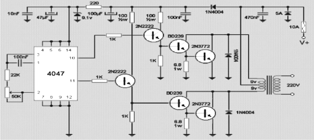
This post explains how to build a simple 12V 200 watt inverter circuit capable pf producing 220V or 120V outpur depending on the transformer used.

The figure above shows the complete circuit diagram of the inverter consisting of an oscillator circuit rigged around the IC 4047, whose frequency can be altered by changing the adjustments of the 50K pot.
The 2N2222 transistor are configured as voltage followers and current amplifiers and are positioned to amplify the small current from the IC to a level which could sufficient enough to drive the subsequent power transistors.
The BD transistor stage are connected to further amplify the current for the final 2N3772 transistor which boosts the current to a massive level and dump the same inside the primary winding of the transformer for the intended induction.
The transformer is now forced to oscillate at the IC 4047 frequency but with full battery current which results in a robust 200 watt of power across its secondary output.
This 220V 200 watt inverter circuit could be used for operating lights, soldering iron small heaters, fans etc, but computer should not be operated since it is a square wave design
Leave a Reply