Right here we research a very easy 120V/220V smps LED driver circuit that can be used for driving high watt LEDs rated any place between 1 watt to 12 watts instantly from any domestic AC mains outlet.

The offered smps LED driver circuit is exceedingly adaptable and in particular fitted to driving high watt LEDs, in spite of this being a non-isolated topology does not give safety from electric shocks at the LED side of the circuit.
Aside from the above disadvantage, the circuit is perfect and is practically guarded from all feasible mains surge related hazards.
Even though a non-isolated configuration may appear a little unwanted, it reduces the constructor from winding complex primary/secondary sections on E-cores, since the transformer here is restored with a few easy ferrite drum type of chokes.
The main element here to blame for the performance of all the capabilities is the IC VIPer22A from ST microelectronics, which has already been specifically made for such small transformerless compact converter applications.
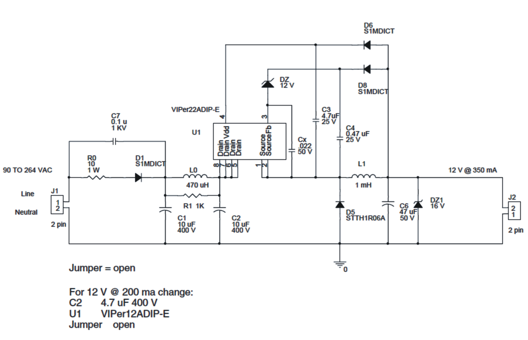
The circuit working of this 1 watt to 12watt LED driver may be known as presented under:
The input mains 220V or 120V AC is half wave repaired by D1 and C1.
C1 together with the inductor L0 and C2 make up a pie filter network for cacelling EMI disturbenaces.
D1 ought to be ideally changed to two diodes in series for preserving the 2kv spikes bursts genareated by C1 and C2.
R10 guarantees some level of surge security and works similar to a fuse throughout catatrophic circumstances.
As may be seen in the above circuit diagram, the voltage acroiss C2 is aplied to the interal mosfet drain of the IC at pin5 to pin8.
An inbuilt continuous current source of the VIPer IC provides a 1mA current to pin4 of the IC which is the Vdd pin of the IC.
At about 14.5V at Vdd, the curent sources gets turned OFF and causes the IC circuitry into an oscillatory mode or initiates pulsing of the IC.
The parts Dz, C4 and D8 turn out to be the circuit regulation network, where D8 charges C4 to the peak voltage in the freewheeling period and when D5 is forward one-sided.
Throughout the above measures, the source or the referance of the IC is set to about 1V below ground.
For an extensive info regarding the circuit information of the 1 watt to 12 watt LED driver, make sure you undergo the following pdf document offered by ST microelectronics.
WARNING: PLEASE ADD A SMALL PIECE OF HEATSINK WITH THE IC, OTHERWISE THE LEDS WILL START FLASHING ON/OFF RAPIDLY AS SOON AS THE IC BECOMES TOO HOT...THEREFORE MAKE SURE THE IC IS NOT ALLOWED TO BECOME HOT, BY ADDING A SUITABLE HEATSINK.
My bulbs driver born through high corrent, can I get replacement from market
yes you can replace from market
dear sir,
can you please share the calculation part of this 9w led driver?
means how the rating of components you have decide?
Sneha, for the calculations please search for the original datasheet of the project.
Dear sir,
Where I can buy this IC VIPer22A? Is there any equivalent IC?
Thanks in advance.
Abhijit, you can easily buy this from big electronic retail shops, or online also. There’s no equivalent for this….a different equivalent is there in the form of TNY267 IC, but the circuit is different
Pl. any idea about the pcb design available.
Any answers pl post or email me.
sorry there’s no PCB for this project
where is this IC available
Lamington Road Mumbai
How did you calculated value of capacitor ?
it’s as per the datasheet
Hello sir , Please u can tell me what is exact unit of C7 ad Cx capacitor that mention in circuit diagram. Please reply as soon as possible. This circuit is work with the 230v 50hZ frequency
The values are already given in the diagram. Yes it will work with 220V input
Hello sir i want the detail pdf of this circuit plz u can provide me on my email id
Sorry Abhishek, I don’t have it!
my specific requirement : 1) output for 1w,LED, 3.3 vdc ,330 MA ///// 2) I/P 100-280 V AC
+ 1W POWER LED MOUNTED ON SUITABLE HEATSINK
3) ISOLATED OUTPUT / AND SHORT CIRCUIT PROTECTED
WHAT cost i can get the assembled pcb ? who can supply ? ( I AM FROM PUNE , IS IT POSSIBLE TO MEET – I HAVE SOME IDEA TO BE TRIED (which can be cost effective / remote control led/ intensity control and color / control //easy to repair or modular construction — in my opinion
CAN I GET FEW FOR TRIALS ?
contact homemade-circuits(dot)com those guys can perhaps help!
Hi,
i need this circuit.
Please let me know the cost of the product.
Can you help me in designing the 12watt driver. I have one 7watt driver and I want to convert it to 12 watt driver.How to select the capacitor value in order to increase the watt in the same driver circuit.
you will have to show me the schematic to understand its working and modifications….
Sir it is very informative I have learnt many thing bt it is not enough to repair led bulb circuit. My main aim is to repair led bulb circuit so plz give information abt led diagram
thanks kabir, please ask your specific questions ….I’ll try to help
Dear sir
this is mahesh here i want to design led driver for 9w with 1 year warranty so can i can get the circuit for that and the circuit should be simple please provide me the all details my mail id is ‘bmahesh770@gmail.com’
Dear Mahesh, the diagram is already presented in the above article, which you can use but the LeDs will need to be 1 watt LED, 9 in series
THANKS FOR YOUR QUICK RESPONSE – ALSO TELL WHERE IS THE PDF LINK
OF ST MICRCO ELECTRONICS
you can find it embedded in this article
simple-1-watt-to-12-watt-smps-led/
YOU HAVE NOT GIVEN EQUIVALENTS FOR THE DIODES USED
USE BA159 FOR D5 AND REST CAN BE 1N4007
How the value of L1 is selected???
it is as recommended by the manufacturer of the IC
Sir I want to make a led driver with 18w
sorry, Presently I do not have an 18W circuit…
Hello sir,
Im tushar khaire from nasik maharashtra.sir want get a detail knowledge about the led bulb and solar base product. Can you provide me the knowledge of this.
Please reply.
Thanks and regards.
Tushar khaire
Hello Tushar,
you can ask your specific questions, I’ll try to answer them as far as possible.
Above circuit diagram is for 4.2W no?(12v *300 ma)
pls post the circuit diagram for 9W..(12v*750ma)
the voltage can be increased upto 40V, you can connect series LEDs and get wattage output upto 40 x 0.3 = 12 watts…but current cannot be increased
Pls send 1-12w changing parts list
how to change output wattage plz send change component list
output wattage can be changed by increasing the output voltage which can be done by increasing the zener diode value DZ1, this will allow you to put more number of 1 watt LEDs in series and increase the output power
HII,
MYSELF AKASH FROM WEST BENGAL. I AM INTERESTED TO MANUFACTURE LED BULB AND OTHER LED RELATED DRIVER. I WANT LED DRIVER CIRCUIT(0-18 WATT) . I WANT ALSO PLEASE TELL ME THE MACHINE COST FOR MAKING DRIVERS AND OTHER ELECTRONICS ITEMS . IF POSSIBLE I WANT A TANNING FOR HOW THE PRODUCTION LINE WORKS AND HOW TO DO CIRCUITS.
PLEASE INFORM ME ph-9474177902
If possible give me your mail id or ph no.
The above circuit is the perfect one and is very reliable, you can apply it for making 1 to 12 wtt LeD drivers..if you have any specific questions you can feel free to ask them here
How do you get around the eletric shock issue. Isn’t there anything that you could do about that?
It is a non-isolated design and therefore danger of shock will be there, however since the entire unit along with the LeDs would be enclosed inside a plastic box, the user would be safe from any kind of electric shocks..
I want to give tranning led bulb production please help and sugest me
you will get training here, please provide all the details of your production requirement, meaning the specifications of the LED bulb which you want to manufacture
mere ko job milega iti electronic
what kind of job do you want