IN THE 220 V touch switch lamp circuit explained during this project, it was described how the action of the switch needs to be touch on touch off, and that no actual connection with the circuit be generated (pertaining to security purposes).
Most of these difficulties directed us to employ a capacitive circuit. The touch plate is in impact a capacitor.
When this plate is touched, the input of the first stage is capacitively referenced to ground, nevertheless as the supply rails to the control circuit are floating at rectified 120Vac the 60 Hz waveform efficiently shows up at the input of the control circuit and starts the switch action.
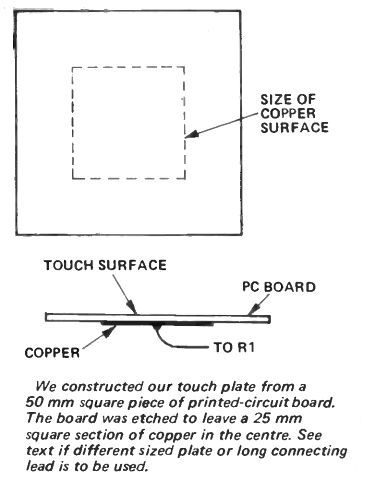
The actual contact plate is a piece of single sided printed circuit board organized hence the the non copper side is touched ,the copper on the reverse side is attached to the control circuit.
CONSTRUCTION
A 220 V touch switch lamp circuit might be built (and utilized) in numerous various ways. It might be installed within the base of a lamp; fitted onto a conventional switch plate to control overhead lights; or installed in a piece of electronic equipment.
It is on the other hand impossible how the switch will be employed as a separate unit and therefore housing details is not provided. Mentioned previously above the touch plate is made with a piece of printed circuit board as detailed in the drawing.
The touch plate does not have to be precisely as revealed however could be almost any effortless shape or size. Even so ensure that the copper surface of the plate are not able to touch any of the external metal surfaces and that it may not be touched with the fingers.
In case the unit would be to constructed into a lamp that includes a plastic base a piece of aluminium foil might be glued into the inner surface of the base to behave as the pickup plate.
If the plate is simply too large or maybe the lead linking it towards the circuit very long, stray capacitance to ground might be adequate to avoid the switch functioning.
If the lead is greater than around 50 mm long shielded cable needs to be applied (shield linked to '0' volts not to ground). If a large plate is employed the gain of the first stage needs to be decreased by changing the value of R2. (Attempt 3.3 M first in case it works successfully try out 1 M).
The 220 V touch switch lamp circuit provided in the main circuit diagram supplies the load with pulsating dc and is as a result ideal to drive resistive loads (for instance light bulbs) only. If an inducive load needs to be supplied the somewhat more complicated substitute circuit (demonstrated in the insert) should be employed.
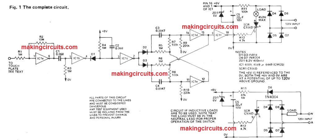
Within this circuit the load needs to be inserted in the neutral lead if the switch is to function effectively. As a result it is recommended make sure that the active and neutral are generally attached in the correct way.
How the Circuit Works
POWER SUPPLY
The 120 Vac is rectified by diodes D4 to D7. The output of the diode bridge is then lowered, smoothed and controlled to 6 volts dc through R11, ZD1 and CS.
The load is attached using the rectifier and possesses power switched to it through the silicon controlled rectifier, SCR. Be aware especially that the load is provided with pulsating de hence, kind of load applied using this circuit needs to be resistive, for instance, an incandescent lamp.
For inductive loads just like transformers etc, the load circuit needs to be improved as demonstrated in the small diagram.
DETECTOR
The detector is built by one section of a CMOS hex inverter, IC1a, where the gain is set by the ratio of R2/R1. The touch plate is attached to the input of the detector and touching it successfully adds a capacitor to ground.
Though the '0' volt line (because of the diodes D4 to D7) when referenced to ground is appropriately 60 Hz 120 volt rectified. The touch plate capacitance presented for that reason couples this waveform into the input of the detector and also drives the amplifier in order that the output is a 60 Hz squarewave.
In case the plate is not touched the capacitance is certainly much lower and therefore the output of the amplifier is really a lot lower in level. The sensitivity might be modified by changing the value of R2 (lower value provides less sensitivity).
LEVEL SHIFTER
The output of IC1a is centered around 3 volts, and C1, R3 and IC1b widely-used to deliver level shift in a way that the output of IC1b is generally high at +6 volts till the plate is touched.
Once the plate is touched the output of IC1b oscillates among +6V and OV at a 60 Hz rate. The hex -inverter IC has diodes internally which link each input to ground. Hence these diodes avoid the inputs from being driven below -0.6 volts.
PULSE STRETCHER
The 60 Hz output from IC1b is not really in a handy form and needs to be transformed into a signal which can be only high and remains high whilst the plate is touched. This really is conducted by a pulse stretcher and inverter comprising IC1 c combined with R4 and C2.
The output of IC1c is usually low and proceeds high and stays high whilst ever the plate is touched.
FLIP FLOP
To meet our mode of operation the circuit is required to be placed on after the finger is taken off the plate and only turned off when the plate is touched a second time.
Hence a toggle action is needed which is acquired by including a flip flop formed by IC1d and IC1e. Cross coupling of gates usually offers an RS flip flop which might take up any state if both inputs are taken high collectively.
Because of this the capacitors, resistors and diodes at the inputs to the flip flop are employed to present steering logic to make sure that correct toggle action is gathered.
BUFFER
To avoid loading the flip flop, and since a spare section of the hex inverter is obtainable, a buffer amplifier is placed amongst the flip flop and the SCR.
The SCR utilized is a C106D which is actually a sensitive gate type. This type of SCR will function dependably along with the 1 mA gate current supplied. The SCR described will probably be applied, avoid to attempt alternatives.
Leave a Reply