• Skip to main content
  • Skip to primary sidebar

Making Easy Circuits

Learn and build electronic circuits

You are here: Home / Indicators / 3 LED Battery Monitor Circuit

3 LED Battery Monitor Circuit

Last Updated on May 15, 2020 by Admin Leave a Comment

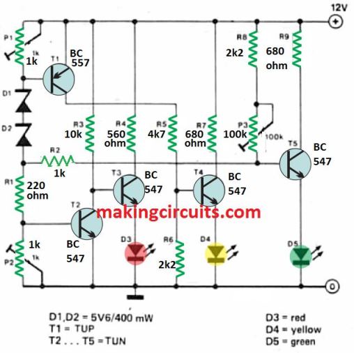
This battery monitor circuit can be used to monitor the charge level of a battery in 3 different steps, indicated by 3 separate LEDs.

Just three LEDs are incorporated to provide an indication of the car (or boat) battery condition.

The LEDs light as follows: Preset P2 sets the voltage above which D3 goes out (13 V);

How the Circuit Works

P1 sets the point at which D4 lights (12 V); lastly, P1 sets the voltage above which D5 lights (14 V).

The calibration technique is, somewhat crucial, and will have to be repetitive many times considering that the numerous changes influence one another.

battery monitor circuit

The image displays the author's prototype.

All components are fitted in a small plastic tube, with the LEDs at one end and a ' cigarette lighter' plug at the other.

This 3 step battery monitor circuit can then effortlessly be connected to the corresponding socket on the dashboard for a speedy check of battery situation.

If the proposed colours are used for the different LEDs, red will correspond to 'battery low'; yellow (with or without red) signifies ' battery normal'; and green will generally light once the battery is ' on charge'

You'll also like:

  • 1.  How To Make Battery Charging Fault Indicator Circuit
  • 2.  How to Build a Logic Level Indicator Circuit
  • 3.  Automatic Light Circuit for Washroom  
  • 4.  Simple Digital Voltmeter Circuit
  • 5.  Automotive Speed Limit Indicator Circuit
  • 6.  Walking Distance Counter Circuit

About Admin

Hey friends, Thanks a bunch for stopping by this site! I am an engineer with a Bachelor of Engineering in Electronics and Telecommunication. One of my passions is gathering information from all sorts of electronics books and tutorials. I then take that information and compile it into a language that is super easy to understand. My goal is to make those complex electronics circuit concepts and technical terms much more accessible for all the new and budding electronics engineers out there. I can also design customized circuit diagrams as required by the users.
If you have any questions related to this field, please do not hesitate to drop a comment! I am always here and ready to help you out with any queries you might have. I cannot wait to hear from you!

Reader Interactions

Leave a Reply Cancel reply

Your email address will not be published. Required fields are marked *

Primary Sidebar

Categories

  • 3 Phase (4)
  • 8051 Microcontroller (1)
  • Arduino (11)
  • Audio and Amplifier (102)
  • Automation (8)
  • Battery Chargers (64)
  • Bicycle Projects (4)
  • Car and Motorcycle Projects (39)
  • Datasheets (10)
  • DIY Projects (5)
  • Electrical (15)
  • Free Energy (6)
  • Games Projects (2)
  • High Voltage (14)
  • Hobby Projects (30)
  • Household Circuits (2)
  • IC 555 Circuits (4)
  • Ignition Circuits (2)
  • Indicators (50)
  • Infrared (6)
  • Inverter Circuits (29)
  • Lights and Lamps (97)
  • Medical (8)
  • Meter and Tester Circuits (38)
  • Motor Driver (17)
  • New Circuits (56)
  • Oscillators (30)
  • Pets and Pests (5)
  • Power supply (81)
  • Protection Circuits (25)
  • PWM (8)
  • Remote Control (20)
  • Security and Alarm Circuit (48)
  • Sensors and Detectors (66)
  • Signal Processor (23)
  • Solar Controller Circuits (61)
  • SSR (3)
  • Temperature Controller (20)
  • Timer (25)
  • Transformerless (7)
  • Transmitters (12)
  • Tutorials (45)
  • UPS (2)
  • Voltage Regulators (57)
  • Water Sensor and Controller (29)
  • Home
  • Privacy Policy
  • Contact
  • Disclaimer
  • Copyright

© 2025 · Making Easy Circuits