The post offers a 32V, 3 amp SMPS circuit which can be in particular useful for operating 100 watt LED components, rated with similar specifications.
The circuit of the offered 32 V, 3 amp smps led driver might be known with the the guide of the following points:
The mains voltage is improved and filtered by the bridge network and the relevant filter capacitor C1. This rectified 310 V DC transmits through R1, R2 and causes T1 into conduction.
T1 switches ON and draws this DC to ground by means of the 30 + 30 primary winding activating a steep pulse during this winding and also across the lower auxiliary winding.
This pulse across the auxiliary winding allows a negative pulse to be produced at the junction of R1/R2 which briefly sinks the base drive to ground such that T1 now shuts off.
At the same time C2 charges up drying up the auxiliary winding consequence, and permits T1 with a fresh initiating potential at its base.
T1 performs yet again and the cycle retains repeating at a frequency dependent upon the value of R2/R3/C2 that may be around 60 kHz right here.
This rapid switching encourages a corresponding voltage and current across the secondary winding which might be more than 32V, 3amps AC according to the presented winding information.
The above voltage is properly filtered by C4 and used across R6, R7 for providing the shunt regulator and the opto coupler phase.
R6 is correctly modified such that the output voltage settles to about 32 V.
The shunt regulator immediately triggers the opto in the event the voltage is likely to get over the set value.
The opto consequently "kills" the base drive of T1 for the moment disabling the primary procedures until the output potential is renewed to the proper value, the opto now produces T1 and permits the functions to function usually, merely until the output goes up once again to start the opto one more time, the method maintains duplicating making sure a continuing 32 V at the output, for driving the 100 watt LED module safely
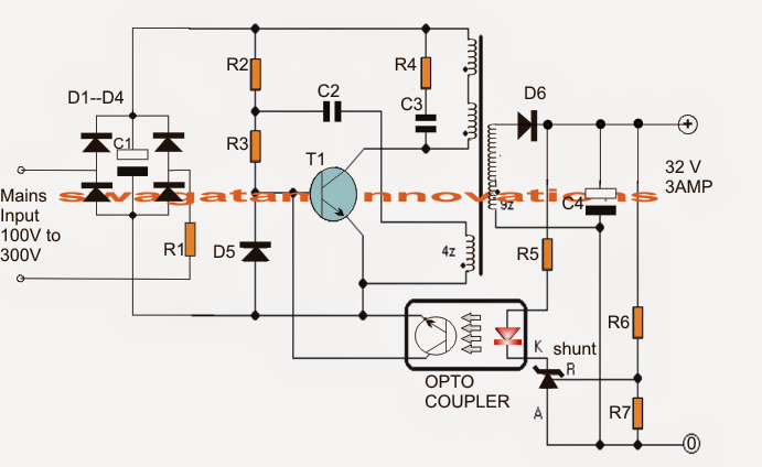
The transformer is wound over a normal EE ferrite core obtaining a central cross sectional area of a minimum of 7 square mm.
Talking about the figure, the upper two primary winding are created up 30 turns of 0.3 mm diameter super enameled copper wire.
The lower primary auxiliary primary winding contains 4 turns of the similar wire as above.
The secondary is wound with 22 turns of 0.6mm super enameled copper wire.
The methods are given below:
First start winding the upper 30 turns, secure its ends on the bobbin turns by soldering, and put a thick layer of insulation tape over these turns.
Next, wind the secondary 22 turns and solder its end terminals on the other side of the bobbin leads, put a layer of thick insulation tape.
Over the above layer start winding the auxiliary 4 turns and as above obtain the ends properly on the primary side leads of the bobbin, again put some layers of insulation over this,
At last, wind the second 30 primary turns beginning with the earlier 30 turn end, and acquire the end over certainly one of the leads of the bobbin on the primary side.
Cover the completed winding with further layers of insulation tapes.
You should definitely be aware of the finished leads correctly so that you will also don't produce wrong connections with the circuit and result in a potential fire danger.
Parts List
All 1 watt, CFR
R1 = 10E
R2 = 1M
R3 = 470E
R4 = 100E
All 1/4 watt MFR 5%
R5 = 470E
R6 = preset 22k
R7 = 2k2
C1 = 10uF/400V
C2 = 2.2nF/250V
C3 = 220pF/1kV
C4 = 2200uF/50V
D1---D4 = 1N4007
D5, D6 = BA159
shunt regulator = TL431
opto = 4n35
T1 = MJE13005
d6 is ba159
ba159 can handel 1amper wy 3amper ?????????????????????????
You are right Ali, so please replace the diode with a 3 amp Schottky diode…
Why do I get 10V 0.5A with a load of 100W(LED)
without load how much voltage do you see?
Has this circuit any current limiting capability?
thanks
No it doesn’t, but a simple modification using the concept shown below can be integrated with the T1 of the above SMPS for ensuring the current controlled feature
https://makingcircuits.com/blog/2015/08/100-watt-current-controlled-led-driver-circuit.html