• Skip to main content
  • Skip to primary sidebar

Making Easy Circuits

Learn and build electronic circuits

You are here: Home / Lights and Lamps / 50 Watt LED Driver Circuit

50 Watt LED Driver Circuit

Last Updated on February 17, 2018 by Admin 1 Comment

The article offers an SMPS centered LED street lamp driver circuit that are available for driving any LED lamp design starting from 10 watts to 50 watts plus.

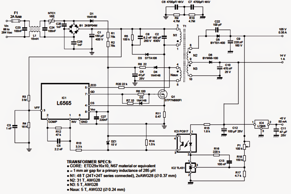
The offered 50 watt (and higher) LED street light driver circuit utilizes the IC L6565 as the main control device, which can be essentially a current mode primary controller chip most definitely developed for quasi-resonant ZVS fly-back converters. ZVS means zero voltage switching.

The chip performs the stated quasi-resonant feature by sensing the demagnetization of the transformer and by consequently switching the mosfet for additional activities.

A feed forward function allows the IC to make up for the variations of the mains voltage which often looks after the converters power managing functions.
In case that the attached load is much less than the chosen magnitude, the device in the same way adjusts and compensates the working frequency without influencing the ZVS feature by much.

Along with the above benefits the IC as well consists of an incorporated current sensor, an error amplifier with precise reference voltage and a flexible two phase protection against overcurrent load circumstances.

More information relating to the IC L6565 are available in its datasheet.

The remaining configuration of the converter is regular and might be known provided below:

The mains 120/220V AC is fed to the bridge rectifier B1 via an EMI filter L1.
The rectified voltage is filtered by C1 and employed on the primary section of the converter which makes up the IC L6565 together with the ferrite transformer primary winding and the switching mosfet.

The IC immediately causes itself and the mosfet, developing the highlighted ZVS procedures and changing the mosfet at the specific compensated rate, based upon the mains input level.

The output of the transformer replies to this and produces the needed voltages across the specific winding.

The outputs are properly rectified and filtered by the associated quick recovery diodes and high voltage filter capacitors.

N2 is generally sen specified with an output of 105V at 350mA.
Other auxiliary winding which can be integrated generate 14V (@1amp) and 5V (@50mA) which can be useful for other appropriate functions for example charging a battery or lighting a pilot lamp.
The opto IC3 is as normal incorporated for providing a continuing output with regard to voltage, current and for giving the appropriate output information to the chip so that the needed protective measures may be required by the chip during undesirable circumstances.

The transformer winding particulars for the suggested 50 watt street light driver circuit is furnished in the diagram itself.

50wattstreetlightcircuit

You'll also like:

  • 1.  How to Generate Infrared LED Flood Light
  • 2.  How to Build a Automatic Night Operated LED Lamp
  • 3.  Power Saving Street Lamp Circuit using Motion Sensor
  • 4.  1.5V LED Flasher Circuit
  • 5.  Make this Garden Solar LED Circuit
  • 6.  LED Bar Mode Chaser/Scanner Circuit [Mustang Style]

About Admin

Hey friends, Thanks a bunch for stopping by this site! I am an engineer with a Bachelor of Engineering in Electronics and Telecommunication. One of my passions is gathering information from all sorts of electronics books and tutorials. I then take that information and compile it into a language that is super easy to understand. My goal is to make those complex electronics circuit concepts and technical terms much more accessible for all the new and budding electronics engineers out there. I can also design customized circuit diagrams as required by the users.
If you have any questions related to this field, please do not hesitate to drop a comment! I am always here and ready to help you out with any queries you might have. I cannot wait to hear from you!

Reader Interactions

Comments

  1. sasan says

    May 18, 2017 at 9:22 am

    hello

    Reply

Leave a Reply Cancel reply

Your email address will not be published. Required fields are marked *

Primary Sidebar

Categories

  • 3 Phase (4)
  • 8051 Microcontroller (1)
  • Arduino (11)
  • Audio and Amplifier (102)
  • Automation (8)
  • Battery Chargers (64)
  • Bicycle Projects (4)
  • Car and Motorcycle Projects (39)
  • Datasheets (10)
  • DIY Projects (5)
  • Electrical (15)
  • Free Energy (6)
  • Games Projects (2)
  • High Voltage (14)
  • Hobby Projects (30)
  • Household Circuits (2)
  • IC 555 Circuits (4)
  • Ignition Circuits (2)
  • Indicators (50)
  • Infrared (6)
  • Inverter Circuits (29)
  • Lights and Lamps (97)
  • Medical (8)
  • Meter and Tester Circuits (38)
  • Motor Driver (17)
  • New Circuits (56)
  • Oscillators (30)
  • Pets and Pests (5)
  • Power supply (81)
  • Protection Circuits (25)
  • PWM (8)
  • Remote Control (20)
  • Security and Alarm Circuit (48)
  • Sensors and Detectors (66)
  • Signal Processor (23)
  • Solar Controller Circuits (61)
  • SSR (3)
  • Temperature Controller (20)
  • Timer (25)
  • Transformerless (7)
  • Transmitters (12)
  • Tutorials (45)
  • UPS (2)
  • Voltage Regulators (57)
  • Water Sensor and Controller (29)
  • Home
  • Privacy Policy
  • Contact
  • Disclaimer
  • Copyright

© 2025 · Making Easy Circuits