The post explains how to build a highly efficient class A/B 60 watt amplifier circuit which is also popularly known as the mini crescendo amplifier.
There are two type 2N3055 power transistors in the output stage, used for their reliability.
Although some may mistake the output stage to be asymmetrical due to the T15 and T16 transistors being NPN, it is, in fact, symmetrical.
Circuit Description
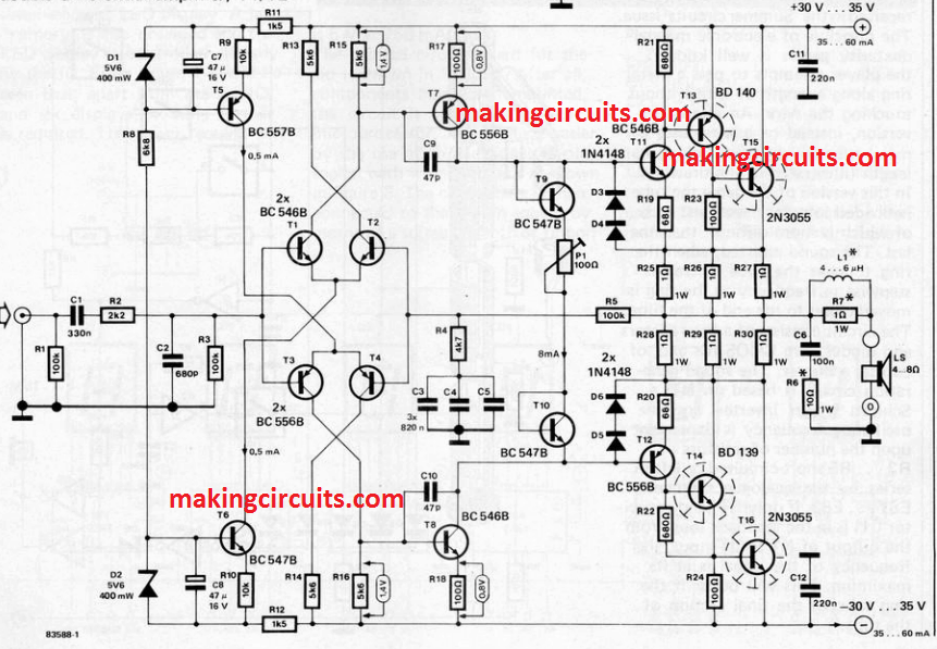
A careful examination will reveal that the upper half contains the T11/T13/T15 NPN supertransistor and the lower contains T12/T14/T16 PNP supertransistor, which are complementary to each other.
This is because their emitters are connected through R25-R27 and R28-R30.
The symmetry is maintained throughout the amplifier in the form of T1/T2 and T3/T4, the double differential amplifier, T5 and T6 as current sources as well as T7 and T8 as the driver stages.
We observe an output power of 40 W into 8 Ω or 60 W into 4Ω when the distortion is not over 0.01% in the range of 20Hz-20 kHz frequency.
Power Output Specifications
The maximum power is 45 W into 8Ω and 65 W into 4Ω when clipping starts. Input sensitivity lies at 800(850) mVeff for 40(45) W into 8 Ω and 700 (725) mVeff for 60 (65) W into 4Ω.
The frequency characteristic stays under 1 dB in the range 15 Hz-100 kHz approximately.
A side-effect of the over 200,000 current amplification, though it is not the only cause, is a low insignificant quiescent current of about 25-50 mA in the output.
A very small cross-over distortion was evident when a spectrum analyzer was used with the prototype circuit, even at minimum resistance due to P1.
P1 is used to set the quiescent current with the help of a universal meter (dc-mV range) connected across the R25-R30 chain of resistors, ie, between the emitter in T15 and the collector in T16.
A 33 mV voltage is equivalent to a 50 mA current.
Construction Hints
A Vero board is used for the 60 watt mini crescendo amplifier circuit as a printed circuit board suitable for the project is not available. So it is best to construct the architecture as close to the circuit diagram as possible.
T15 and T16 require a common sink of 1.5-2°C/W, without neglecting the mica washers. But the heat sinks for T13 and T14 should be separate and of about 12°C/W.
Now, even though the temperature does not alter the output stage in terms of quiescent current for all practical purposes, there's no harm thermally couple T9 with T11 and T10 with T12 by gluing their flat vertical surfaces together.
For designing L1, 0.8-1 mm diameter enameled copper wire is used in 2x10 turns around the R7 resistor.
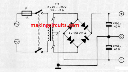
The power supply is normal and current consumption stands at 1.0 (1.06) A for 40 (45) W into 8 Ω and 1.75 (1.81) A for 60 (65) W into 4 Ω.
Hi,
I built the original Mini Crescendo by Elektor, 15 years ago and directly replaced the 2SK125 with a 2N3055, and the 2SJ50 with a 2N2955 (Metal-Transistor). Just a note: a larger heatsink is required. It’s still working flawlessly, delivering excellent sound quality with no issues.
Thanks for your feedback!
please..where is PCB layout this scheme..thank you
PCB you can find on homemade circuits website under 100 watt mini crescendo article…