In this post we learn about a simple single cheap 70 watt high efficiency power amplifier circuit using the IC TDA1562
FUNCTIONAL DESCRIPTION:
The TDA1562Q consists of a mono class-H BTL output power amplifier.
During lower output power, approximately 18 W, the system works like a typical BTL amplifier. If a much larger output voltage swing is necessary, the internal supply voltage will be elevated by using the external electrolytic capacitors. Because of this for a few seconds increased supply voltage the accessible output power becomes 70 W.
Within regular use, once the output is powered using music-like signals, the high output power is barely required throughout a modest portion of time. With the supposition that a audio signal includes a regular (Gaussian) amplitude syndication, the decrease in dissipation is approximately 50% while in comparison to a class-B output amplifier using the identical output power.
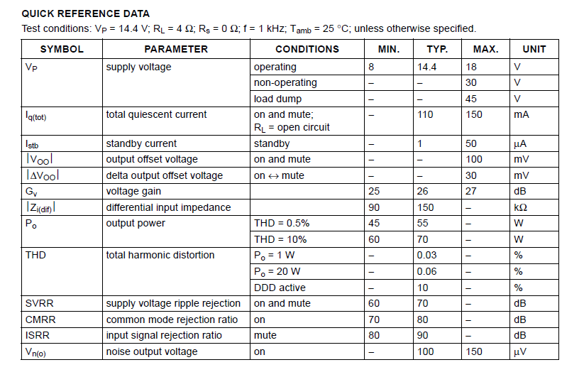
 Technical Specifications for the IC TDA1562
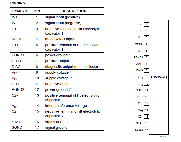
Pinout Description:
If you have any more doubts regarding this TDA1562 70 watt high power amplifier circuit, please put them in the comment box.
Disculpen pero funciona este amplificador
100%
Thanks for the schematic diagram. I barely need that.AWESOME!
You are most welcome Eva!