• Skip to main content
  • Skip to primary sidebar

Making Easy Circuits

Learn and build electronic circuits

You are here: Home / Lights and Lamps / 9V Tubelight Inverter Circuit

9V Tubelight Inverter Circuit

Last Updated on November 27, 2024 by Admin Leave a Comment

In this article we will learn how to make an easy 9V fluorescent tube inverter circuit using ordinary parts such as IC 555 and a cheap 0-6V/220V step down transformer.

As shown in the diagram below, the IC 555 is wired in its most standard configuration of an astable multivibrator meaning in this mode the IC will begin generating pulses at its pin#3 at a frequency rate that may be directly dependent on the selected resistors and capacitor across its pin#6/2.

The output from pin#3 which is in the form DC high frequency is applied to an attached mosfet, and this mosfet is in turn rigged with a step down transformer’s 6V winding for executing the intended 6V to 220V DC to DC inverter circuit.

 tube 1

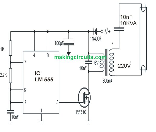
This implies that the IC 555 along with the transformer mosfet driver acts like a small DC to DC inverter for generating a 6V to 220V output.

This 220V may not exactly an AC because it lacks the negative half cycles and delivers only half wave pulsed 220V DC.

However this 220V pulsed DC becomes enough for illuminating a 9V fluorescent tube light brightly.

Therefore this simple 9V tubelight inverter circuit very efficiently cheaply enables any small fluorescent to be illuminated from a 6V battery or any 6V DC power supply.


You'll also like:

  • 1.  12V Battery Fluorescent Light Circuit (20W)
  • 2.  Automatic Street light circuit
  • 3.  Circuit for a Simple, High-Efficiency LED Torch
  • 4.  6V to 12V Boost LED Emergency Light Circuit
  • 5.  Very Simple Emergency Lamp Circuit Using a Single Transistor
  • 6.  Li-Ion LED Driver Circuits using LT1932

About Admin

Hey friends, Thanks a bunch for stopping by this site! I am an engineer with a Bachelor of Engineering in Electronics and Telecommunication. One of my passions is gathering information from all sorts of electronics books and tutorials. I then take that information and compile it into a language that is super easy to understand. My goal is to make those complex electronics circuit concepts and technical terms much more accessible for all the new and budding electronics engineers out there. I can also design customized circuit diagrams as required by the users.
If you have any questions related to this field, please do not hesitate to drop a comment! I am always here and ready to help you out with any queries you might have. I cannot wait to hear from you!

Reader Interactions

Leave a Reply Cancel reply

Your email address will not be published. Required fields are marked *

Primary Sidebar

Categories

  • 3 Phase (4)
  • 8051 Microcontroller (1)
  • Arduino (11)
  • Audio and Amplifier (102)
  • Automation (8)
  • Battery Chargers (64)
  • Bicycle Projects (4)
  • Car and Motorcycle Projects (39)
  • Datasheets (10)
  • DIY Projects (5)
  • Electrical (15)
  • Free Energy (6)
  • Games Projects (2)
  • High Voltage (14)
  • Hobby Projects (30)
  • Household Circuits (2)
  • IC 555 Circuits (5)
  • Ignition Circuits (2)
  • Indicators (50)
  • Infrared (6)
  • Inverter Circuits (29)
  • Lights and Lamps (97)
  • Medical (8)
  • Meter and Tester Circuits (38)
  • Motor Driver (17)
  • New Circuits (56)
  • Oscillators (30)
  • Pets and Pests (5)
  • Power supply (80)
  • Protection Circuits (25)
  • PWM (9)
  • Remote Control (20)
  • Security and Alarm Circuit (48)
  • Sensors and Detectors (66)
  • Signal Processor (23)
  • Solar Controller Circuits (62)
  • SSR (3)
  • Temperature Controller (20)
  • Timer (25)
  • Transformerless (7)
  • Transmitters (12)
  • Tutorials (45)
  • UPS (2)
  • Voltage Regulators (57)
  • Water Sensor and Controller (29)
  • Home
  • Privacy Policy
  • Contact
  • Disclaimer
  • Copyright

© 2025 · Making Easy Circuits