To measure frequency one does not immediately have to ‘go digital’. The analogue approach will invariably prove simpler and cheaper, in particular when the analogue readout (the multimeter) is already to hand.
All that is needed is n a plug-in device, a ‘translator’, that will give the meter an input it can ‘understand’.
This design is based upon an integrated frequency-to-voltage converter, the Raytheon 4151.
The device a is actually described as a voltage-t0 frequency converter; but it becomes clear from the application notes that there is more to it than just that.
The linearity of the converter IC is about 1%, so that areasonably good mul timeter will enable quite accurate frequency measurements to be made.
Because the 4151 is a little fussy about tithe waveform and amplitude of its input signal, the input stage of this design is a limiter-amplifier (comparator).
This stage will process a signal of any shape, that has an amplitude of at least 50 mV, into a form suitable for feeding to the 4151.
The input of this stage is protected (by diodes) against voltages up to 400 V p-p. The drive to the multimeter is provided by a short circuit-proof unity-gain amplifier.
The circuit
Figure1 gives the complete circuit of I the frequency plug-in. The input is safe for 400 V p-p AC inputs only when the DC blocking capacitor is suitably rated. The diodes prevent excessive drive volt ages from reaching the input of the comparator IC1.
The inputs of this IC are biased to half the supply voltage by the divider R3/R4.
The bias current flowing in R2 will cause the output of ICI to saturate in the negative direction.
An input signal of sufficient amplitude to overcome this offset will cause the output to change state, the actual switchover being speeded up by the positive feedback through C3.
On the opposite excursion of the input signal the comparator will switch back again, so that a large rectangular wave will be fed to the 4151 input.
The 4151 will now deliver a DC output voltage corresponding to the frequency of the input signal. The relationship between voltage and frequency is given by:
U/f = R9.R11.C5/0.486(R10+p1) V/Hz
The circuit values have been chosen to give 1V per kHz.
This means that a 10 volt f.s.d. will correspond to 10 kHz.
Meters with a different full scale deflection, for example 6 volts, can, however, also be used.
There are two possibilities: either one uses the existing scale calibrations to read off frequencies to 6 kHz, or one sets P1 to achieve a 6 volt output (i.e. full scale in our example) when the frequency is 10 kHz.
The latter choice of course implies that every reading will require a little mental gymnastics!
With some meters it may be necessary to modify the values of P1 and/or R10; the value of R10 + P1 must however always be greater than 500E ·
The output is buffered by another 3130 (IC3).
The circuit is an accurate voltage follower, so that low frequencies can be more easily read off (without loss of accuracy) by setting the multimeter to a lower range (e.g. 1 V f.s.d.).
The out put is protected against short-circuiting by R12.
To eliminate the error that would otherwise occur due to the volt age drop in this resistor, the voltage follower feedback is taken from behind R12;
To enable the full 10 volt output to be obtained in spite of the drop in R12 (that has to be compensated by the IC) the meter used should have an internal resistance of at least 5 kohm).
This implies a nominal sensitivity of 500 ohm/volt on the 10 volt range.
There surely cannot be many meters with a sensitivity lower than that.
If one has a separate moving coil milliammeter available, it can be fitted with a series resistor that makes its internal resistance up to the value required of a voltmeter giving f.s.d. at 10 volt input.
This alternative makes the frequency meter independent of the multimeter, so that it can be used to monitor the output of a generator that for some reason may have a dubious scale or knob-calibration.
Construction
No trouble is to be anticipated if the circuit is built up using the PC board layout given in figure 2. Bear in in mind that the human body will not necessarily survive contact with input voltages that may not damage the adequately rated input blocking capacitor.
If one contemplates measuring the frequency of such high voltages the circuit should be assembled in a well-insulated box! The power supply does not need to be regulated, so it can be kept very simple.
A transformer secondary of 12 volts, a bridge rectifier and a 470 uF/25 V reservoir electrolytic will do the job nicely. Although a circuit that draws 25 mA is not too well suited to battery supply,one may need or wish to do this.
In this case the battery should be 'bridged by a low-leakage (e.g. tantalum) 10uF/25 V capacitor to provide a low AC source impedance.
Calibration
The calibration can really only be done with an accurate generator.
10 kHz signal is fed to the input and Pl is set to bring the multimeter to full scale deflection (e.g. 10 V).
That completes the calibration although it is wise to check that the circuit is operating correctly by using lower input frequencies and observing whether the meter reading is also (proportionately) lower.


A few specifications:
frequency range: 10 Hz . . .10 kHz
input impedance: > 560 k
sensitivity: 50 mV p-p
max input voltage: 400 V peak
minimum load on output: 5 k (if 10 V out required)
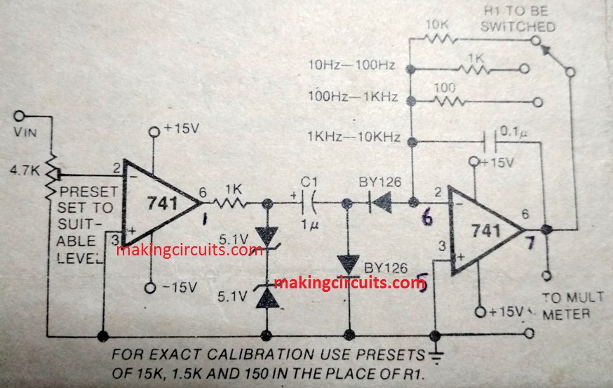
Another Simple Frequency Meter Circuit
The following image shows another design of a frequency meter circuit which is even more simple than the above discussed circuit.
The shown design incorporates just a couple of IC 741, and the output can be connected to any voltmeter circuit for getting the readings.
Leave a Reply