The set up makes it possible to make an simple 12V battery charger of excellent level of quality through which you are able to recharge batteries of 1 2 Volts for car, and dry batteries employed in the systems of alarms.
Its functioning seemingly automatic considering that, whenever it's plugged into a battery, it will eventually only function if the battery is discharged, and it is going to automatically remove when the battery is fully charged.
The unit is driven by a transformer whose secondary is usually 14-15 Volts having a current of 3 Amperes minimum.
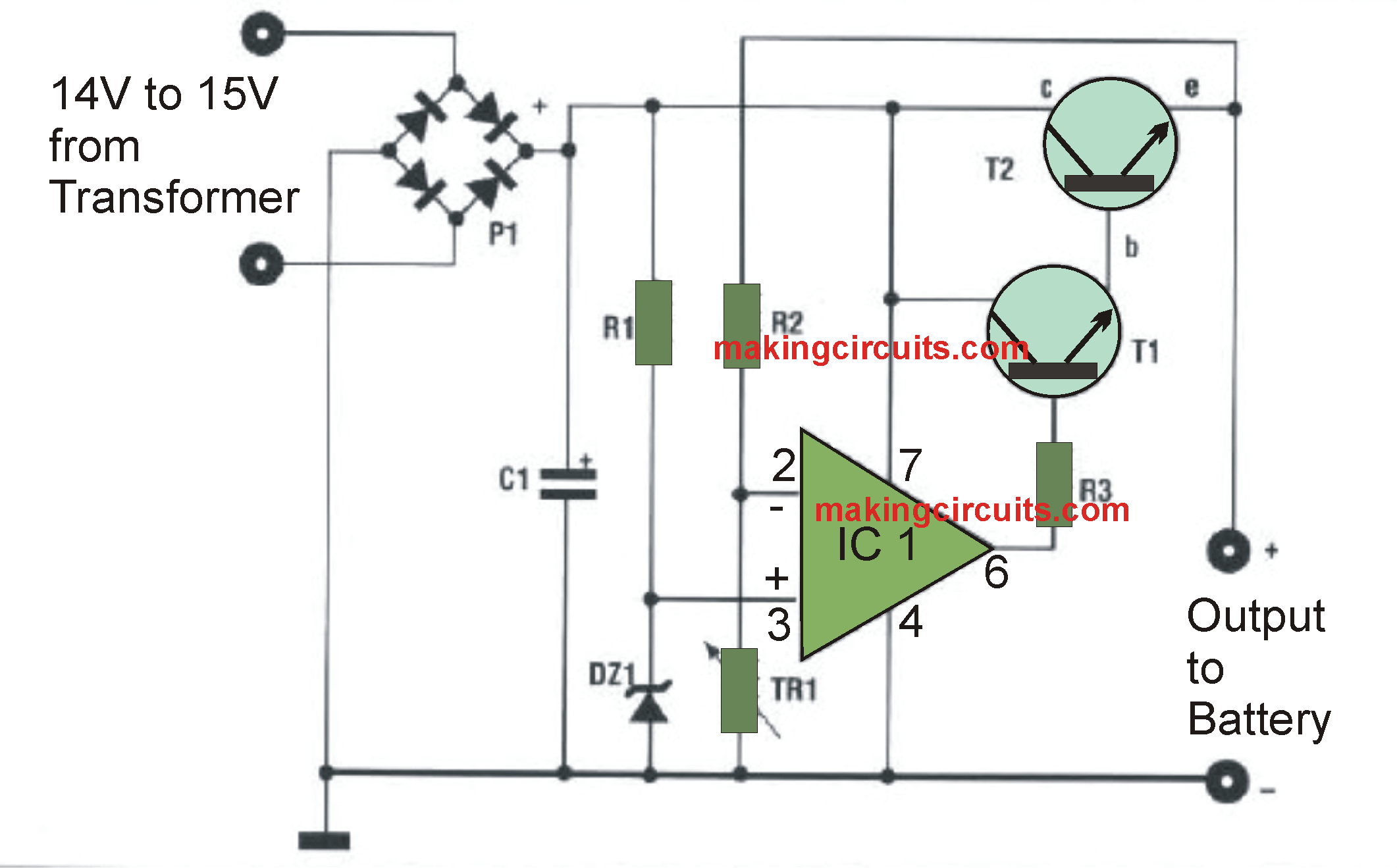
The trimmer TR1 is tweaked to ensure that at the output of the battery charger there exists a voltage of about 14.4 volts without load.
The absolute maximum distributable current is 3 Amperes, so DO NOT make an effort to recharge batteries with a capacity higher than 36Ah. Best utilization of this device would be to power a battery charger for alarm system with battery in standby mode.
In the course of installation, attention should be taken to hook up the battery with the proper polarity.
For the construction of the components, cautiously stick to the configuration of the diagram.
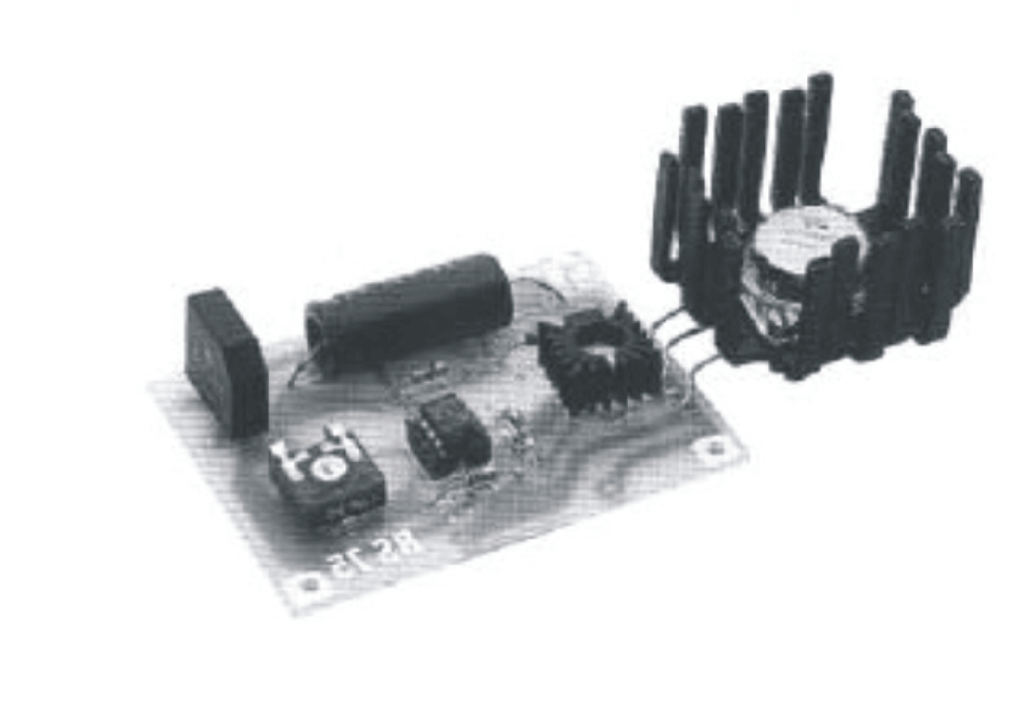
Printed circuit, AUTOMATIC BATTERY CHARGER INPUT 14-15 VOLTS at a charging CURRENT of MAX 3 AMPERES

Parts List for the 12V automatic car battery charger circuit:
All resistors are
Of 1/4 watt unless otherwise specified.
Rl-470 Ohms
R2 = 10 K
R3 = 270 Ohms
TR1 = 10 K trimmer.
Cl = 1000uF25V.
DZ1 = 5.1 volts lWzener.
T1 = 2N2218
T2 = 2N3055-BDW21C
1C1 = UA741
PT1 = KBL04 / 01
1 Socket 8 pins.
1 Heat sink for Tl.
1 Heat sink for T2.
Simple 12V Battery Charger with Battery Indicator
This is a simple 12V battery charger circuit with indicator circuit is a smart charger circuit. You are able to ideally take advantage of this circuit for applications such as inverters, portable chargers, etc. This design additionally includes a twin indication system in the form of a battery charging indicator, and a low battery buzzer indicator. The benefit of this indicator is that a buzzer notifies you once the battery has to be recharged. This circuit design undoubtedly aids for your daily life battery charging purposes.
How the simple battery charger circuit works
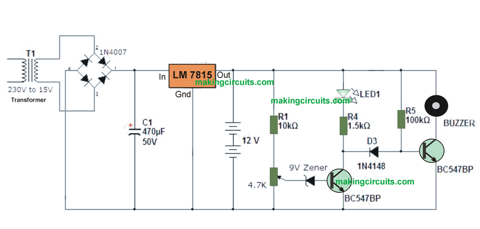
- The charging circuit is created around voltage regulator IC 7815 and a couple of BC transistors 547 BJTs.
- The main 230V or 110V input could be the first steped down through a step-down transformer, after that it may be rectified and filtered.
- This DC voltage is then delivered to the voltage regulator IC 7815 ;. The output gets regulated at 15V
for charging the connected 12 volt rechargeable battery at the output of the voltage regulator. And it begins charging the battery as soon as the main power is available.
- Any time battery voltage falls under a particular value LED1 ceases to glow and the buzzer begins sounding indicating that the battery is discharged and requires recharging.
Bill of Material
-transformer (230V to 15V or 110V T0 15V)
-pont rectifier (1N4007 x 4)
-condenser (470UF, 50V)
- IC 7815 Voltage Regulator
-12V rechargeable battery
Can someone explain me how we calculate the resister values using transistor data sheet. Can some one explain it to me I can pay for onlline session.Please this is where I am having doubts in electronics
Yu don’t have to pay anything, you can go to homemade-circuits blog and solve all your queries regarding electronics…
That isn’t always true my 10 amp charger only measures 10 volts at the output on open circuit, yet it fully charges lithium ion 12 volt cells as well as 12 volt L.A. batteries. Even though it only measures 10 volts it still charges the batteries to 15 volts if left long enough. I beleive this is because it uses the high current to somehow boost the voltage. Inside the charger is nothing more than a simple led display circuit, bridge rectifier, short circuit cutout and a big transformer which only measures 8 volt AC on the output. But thanks for the circuit ideas anyway.
That sounds highly impossible. How can a 10 V supply charge a 12 V battery??
plz provide all round any kind of battery charger ckt dig which has fast charging with auto cuttoff and short ckt protection and also battery level indicator all in one
Dear Sir
for the Simple 12V Battery Charger Circuits with Auto Cut-off Circuit
i would like add charging status indicator(LED) please advice me where to connect the LED
Thank you
Dear Chris,
Add one LED in series with R3, but make R3 1K or 2k2 or 4k7. This LED will indicate that battery is charging. Add another LED with a series 1K resistor across the positive line and the pin#6 of the op amp. This LED will light up when the battery is full.
Hi
To me if the LED is on, the buzzer will also be on as both transistor are on . Another question is what is meant by battery voltage falls below particular value what vale u mean zener voltage of 9v
Ta
Hi, when the LED is ON, means the left side transistor ON, if left side transistor is ON then the right side transistor will be OFF
the particular voltage level will depend on the adjustment of the preset, which could be adjusted depending on the battery full charge level…..
Hi dear;
In the first schematic can we parallel two or more 2n3055 for increasing the output current for charging 100ah batteries??
Yes that may be possible, but you must put all the transistor over a single common heatsink with appropriate mica isolation
sire can i use 12v 15amps transformer instead of 14-15v ??
No, 12V battery can be charged with only 14V or 14.5V
To charge battery more than 36Ah means upto 65Ah or more what changes can be made in the ckt. and can add Auto cut off ckt to this. Plz let me know
Increase the input current to 10 amp that’s all!