• Skip to main content
  • Skip to primary sidebar

Making Easy Circuits

Learn and build electronic circuits

You are here: Home / Lights and Lamps / How to Build a Automatic LED Candle Light Circuit

How to Build a Automatic LED Candle Light Circuit

Last Updated on February 17, 2018 by Admin Leave a Comment

The submit talks about a basic transformerless LED candle light circuit which switches ON automatically without the presence of ambient light in the room and vice versa.

led2Bcandle2Blight2Bcircuit
The suggested automatic darkness activated candle light circuit can be viewed in the demonstrated diagram which utilizes an amber colored LED for simulating a candle light impact.
According to the demand the circuit ought to be LDR based which also means the unit must trigger as soon as it's adequately dark inside the room or the moment the main indoor lights are switched OFF, or when the user goes to bed.
The displayed automatic LED candle light is extremely uncomplicated and relatively dependable with its procedures, let's figure it out by means of the following justification:
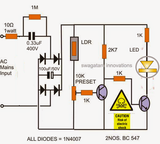
The 0.33uF/400 V capacitor together with the four diodes and capacitor forms a portable transformerless power supply circuit stage for operating the LED during dark or without having ambient light.
The first transistor from left in the existence of ambient light circumstances obtains adequate base drive via the LDRs lower resistance and performs to maintain the base of the second BC547 at ground potentials.
As a result of this the second transistor continues to be inactive and switched OFF making certain that the associated LED also remains to be turned OFF under such ambient external illuminations.
Nevertheless whenever the ambient light around the LDR decreases or is shut OFF, the left transistor is inhibited from the base drive as a result of the LDRs high resistance without having ambient light, which additional encourages the right hand side transistor to begin carrying out, consequently activating the LED.
The opposite reaction is immediately shown in the event the ambient light is turned on or in the course of daybreak.
Caution: The circuit is not isolated from mains voltage, utmost care and precaution is predicted from the user wile putting together, examination, placing the unit in operated circumstance.
The LDR needs to be properly enclosed inside an appropriate cover such that the LED light by no means attains it under any specific situation, elsewhere it might result in false activating and oscillations of the circuit and the LED.
The publish represents an easy transformerless LED candle light circuit which switches ON automatically without the presence of ambient light in the room and vice versa.
The presented automatic darkness turned on candle light circuit can be watched in the presented diagram which employs an amber colored LED for simulating a candle light result.
In accordance with the inquiry the circuit is required to be LDR based which also means the unit must actuate only after it's properly dark inside the room or the moment the main indoor lights are switched OFF, or when the user goes to bed.
The displayed automatic LED candle light is quite simple and quite trustworthy with its functions, let's are aware of it by way of the following clarification:
The 0.33uF/400 V capacitor in addition to the four diodes and capacitor forms a lightweight transformerless power supply circuit stage for running the LED during dark or without any ambient light.
The first transistor from left in the occurrence of ambient light problems experiences enough base drive via the LDRs lower resistance and carries out to continue the base of the second BC547 at ground potentials.
Due to this fact the second transistor continues to be inactive and switched OFF ensuring that the hooked up LED also remains to be turned OFF under such ambient external illuminations.
In spite of this whenever the ambient light around the LDR reduces or is shut OFF, the left transistor is inhibited from the base drive on account of the LDRs high resistance without having ambient light, which even more guides the right hand side transistor to commence executing, and thus activating the LED.
The opposite reaction is instantly shown just in case the ambient light is activated or throughout daybreak.
Caution: The circuit is not isolated from mains voltage, utmost care and precaution are estimated from the user wile building, assessing, fitting the unit in driven condition.
The LDR ought to be correctly enclosed inside the right cover such that the LED light certainly not grows to it under almost any problem, normally it could produce false switching on and oscillations of the circuit and the LED.

You'll also like:

  • 1.  DIY Emergency Lights: 10 Circuit Ideas
  • 2.  How to Make Digital Christmas Candle Light Circuit
  • 3.  Simple Strobe Light Circuits using Transistors
  • 4.  8 LEDs Light up Sequentially, then Shut OFF and Repeat: Circuit Diagram
  • 5.  How to Build a Energy Saving Automatic LED Light Controller Circuit
  • 6.  Low-Cost LED Lamp Circuit Powered by Phone Charger

About Admin

Hey friends, Thanks a bunch for stopping by this site! I am an engineer with a Bachelor of Engineering in Electronics and Telecommunication. One of my passions is gathering information from all sorts of electronics books and tutorials. I then take that information and compile it into a language that is super easy to understand. My goal is to make those complex electronics circuit concepts and technical terms much more accessible for all the new and budding electronics engineers out there. I can also design customized circuit diagrams as required by the users.
If you have any questions related to this field, please do not hesitate to drop a comment! I am always here and ready to help you out with any queries you might have. I cannot wait to hear from you!

Reader Interactions

Leave a Reply Cancel reply

Your email address will not be published. Required fields are marked *

Automatic LED Candle Light Circuit

Last Updated on November 14, 2024 by Admin Leave a Comment

The post describes a simple 220V  mains transformerless LED candle light circuit which switches ON automatically in the absence of ambient light in the room and vice versa. The idea was requested by Mr. Don

Technical Specifications

I only dabble with electronics here and there but in trying to move from incandescent and CFL's to LED's I have come across a strange dilemma.   

I have used electric 110v-120v "Sensor Candles" for many years and they employ a very simple circuit of an LDR/Resistor/Switching Transistor on a circuit board about 1/2" square that fits into the body of the candle.

The candles (not flickering) use c7 5-7 watt incandescent bulbs.  The equal c7 LED of about .5 watts do not work in these candles. 

What is it about the LED bulbs that causes them not to work?   Is there a modification that can be done to the existing circuit boards to make them compatible with LED's?   

I have searched all over for electric candles that use LED's and can find none. 

The LED candles that are available are only battery operated.  It boggles my very old and simple mind that the switching transistor does not simply switch the necessary voltage to the LED.

I find it hard to understand why these products have not been produced to function with LED's.  Perhaps this is a product to might want to design for manufacturers.   

I have one grandchild who has a degree in electrical and computer engineering that promised to review the possibilities but other his other priorities have taken precedence, even though I told him that a patent on the idea might be rewarding.

I can send you a candle, circuit board, or whatever information you may require.

Thanks,
Don Jengo

The Design

automatic night activated candle light circuit

The proposed automatic darkness triggered candle light circuit can be seen in the shown diagram which uses an amber colored LED for simulating a candle light effect.

As per the request the circuit needs to be LDR based which also means the unit must activate only when it's sufficiently dark inside the room or as soon as the main indoor lights are switched OFF, or when the user goes to bed.

The presented automatic LED candle light is very straightforward and fairly reliable with its operations, let's understand it through the following explanation:

The 0.33uF/400 V capacitor along with the four diodes and capacitor forms a compact transformerless power supply circuit stage for powering the LED during dark or in the absence of ambient light.

The first transistor from left in the presence of ambient light conditions receives sufficient base drive via the LDRs lower resistance and conducts to keep the base of the second BC547 at ground potentials.

Due to this the second transistor remains inactive and switched OFF making sure that the connected LED also remains switched OFF under such ambient external illuminations.

However as soon as the ambient light around the LDR diminishes or is switched OFF, the left transistor is inhibited from the base drive due to the LDRs high resistance in the absence of ambient light, which further prompts the right hand side transistor to start conducting, thereby switching ON the LED.

The opposite reaction is quickly exhibited in case the ambient light is switched ON or during daybreak.

Caution: The circuit is not isolated from mains voltage, utmost care and precaution is expected from the user wile assembling, testing, installing the unit in powered situation.

The LDR must be appropriately enclosed inside a suitable cover such that the LED light never reaches it under any condition, otherwise it may lead to false triggering and oscillations of the circuit and the LED.

You'll also like:

  • 1.  3V to 5V Boost Circuit for Battery Charging and LED Driver Applications
  • 2.  IC TL494 PWM Modified Sine Wave Inverter Circuit
  • 3.  18 LED Chaser Circuit Diagram Explained
  • 4.  How to Build a Automatic LED Candle Light Circuit
  • 5.  Driver Circuit for CREE XM-L T6 LED
  • 6.  Simple String Light Circuits for Festival Decorations

About Admin

Hey friends, Thanks a bunch for stopping by this site! I am an engineer with a Bachelor of Engineering in Electronics and Telecommunication. One of my passions is gathering information from all sorts of electronics books and tutorials. I then take that information and compile it into a language that is super easy to understand. My goal is to make those complex electronics circuit concepts and technical terms much more accessible for all the new and budding electronics engineers out there. I can also design customized circuit diagrams as required by the users.
If you have any questions related to this field, please do not hesitate to drop a comment! I am always here and ready to help you out with any queries you might have. I cannot wait to hear from you!

Reader Interactions

Leave a Reply Cancel reply

Your email address will not be published. Required fields are marked *

Primary Sidebar

Categories

  • 3 Phase (4)
  • 8051 Microcontroller (1)
  • Arduino (11)
  • Audio and Amplifier (102)
  • Automation (8)
  • Battery Chargers (64)
  • Bicycle Projects (4)
  • Car and Motorcycle Projects (39)
  • Datasheets (10)
  • DIY Projects (5)
  • Electrical (15)
  • Free Energy (6)
  • Games Projects (2)
  • High Voltage (14)
  • Hobby Projects (30)
  • Household Circuits (2)
  • IC 555 Circuits (5)
  • Ignition Circuits (2)
  • Indicators (50)
  • Infrared (6)
  • Inverter Circuits (29)
  • Lights and Lamps (97)
  • Medical (8)
  • Meter and Tester Circuits (38)
  • Motor Driver (17)
  • New Circuits (56)
  • Oscillators (30)
  • Pets and Pests (5)
  • Power supply (80)
  • Protection Circuits (25)
  • PWM (9)
  • Remote Control (20)
  • Security and Alarm Circuit (48)
  • Sensors and Detectors (66)
  • Signal Processor (23)
  • Solar Controller Circuits (62)
  • SSR (3)
  • Temperature Controller (20)
  • Timer (25)
  • Transformerless (7)
  • Transmitters (12)
  • Tutorials (45)
  • UPS (2)
  • Voltage Regulators (57)
  • Water Sensor and Controller (29)
  • Home
  • Privacy Policy
  • Contact
  • Disclaimer
  • Copyright

© 2025 · Making Easy Circuits