• Skip to main content
  • Skip to primary sidebar

Making Easy Circuits

Learn and build electronic circuits

You are here: Home / Indicators / Automatic Plant Irrigation Circuit

Automatic Plant Irrigation Circuit

Last Updated on November 17, 2024 by Admin 10 Comments

The article describes a good automatic plant irrigation system circuit that are available for quickly sensing soil humidity and initiating a water pump when the ground gets burning below a fixed level (adjustable).

The circuit is quite simple and makes use of just one IC 555 as the main active component.

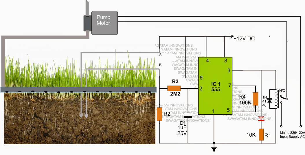
Looking at the automatic plant irrigation circuit demonstrated below we are able to observe the IC 555 is wired in an exclusive and in the fastest feasible mode.
Right here it's designed as a comparator, and functions much better than an opamp simply because the IC 555 has integrated opamps which can be at par with any single opamp as well as the output of a 555 IC has the capacity to sink adequate current to be able to generate a relay without a transistor driver phase.

The above capabilities especially can make the above design quite simple, inexpensive and yet too useful with its features.

The pin#2 right here turns into the sensing pinout of the IC, and is held at ground level via R2 which need to be determined as per the preferred soil humidity activating guideline.

The points A and B may be seen fixed inside the soil which has to be checked for the meant automatic watering from the water pump.

Provided that the points A and B sustains some level of moisture in accordance with a resistance value which might be less than R2, the IC 555 output is held low, which often maintains the relay deactivated.

In spite of this as the soil tends to get dryer, the resistance across the probes begins acquiring higher and at some time of time it gets to be more than R2, producing a potential below 1/3rd supply voltage at pin#2 of IC555.

The above scenario immediately encourages pin#3 of the IC to turn out to be high, initiating the linked relay.

The relay stimulation switches ON the water pump which now commences working water to the specific area of the soil via a publishing water channel.

Since this occur, the soil slowly gets wetter and the moment the specific level is attained, the probes instantly feel the lower resistance and revert the IC ouput pin#3 to a low again changing OFF the relay and the water pump accordingly.

C1 guarantees a slight hysteresis in the procedures making certain the relay activating is not unexpected or sudden, quite it switches only after sensing an original reply from the soil situations.

automaticplantwaterirrigationcircuit

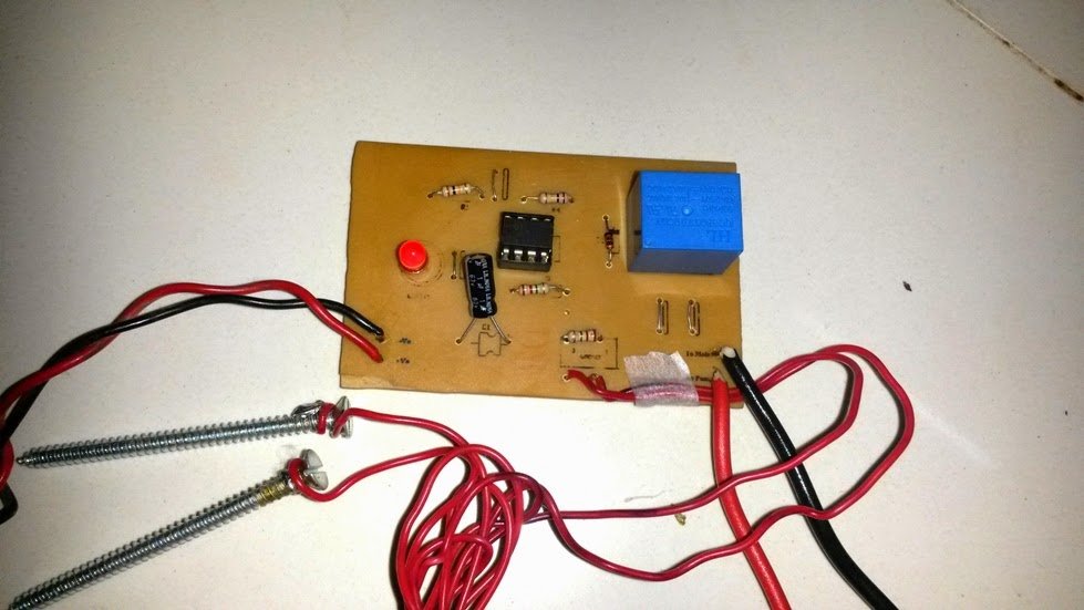
The above stated automatic plant irrigation circuit was effectively developed and analyzed and the
following pictures display the prototype unit and the PCB design.


PlantwateringSystem


PlantWateringSystemPCBLayout

You'll also like:

  • 1.  Keyboard Beep Circuit
  • 2.  Dry Run Protector Circuits using Transistors only
  • 3.  Loudspeaker Power Indicator Circuit
  • 4.  20 watt, 5 watt Fluorescent Lamp Inverter Circuit
  • 5.  Road Diversion Warning Indicator using Running LED Lights
  • 6.  Simple 5 LED Music Level Indicator using a single IC

About Admin

Hey friends, Thanks a bunch for stopping by this site! I am an engineer with a Bachelor of Engineering in Electronics and Telecommunication. One of my passions is gathering information from all sorts of electronics books and tutorials. I then take that information and compile it into a language that is super easy to understand. My goal is to make those complex electronics circuit concepts and technical terms much more accessible for all the new and budding electronics engineers out there. I can also design customized circuit diagrams as required by the users.
If you have any questions related to this field, please do not hesitate to drop a comment! I am always here and ready to help you out with any queries you might have. I cannot wait to hear from you!

Reader Interactions

Comments

  1. Rohith says

    November 21, 2018 at 11:28 pm

    Hi sir can I get this x inverter with 1c 555
    board on shops

    Reply
    • admin says

      November 24, 2018 at 9:18 am

      Hi Rohith, this is not an inverter circuit, do you mean the plant watering board?

      Reply
  2. Raju says

    January 30, 2018 at 6:34 am

    Hiii sir your project is superb . I want to go this project, I’m doing mini project may I connect the small DC motor to run the same operation could you plzzz tell me sir

    Reply
    • admin says

      February 8, 2018 at 9:51 am

      Hi Raju, yes you can connect a small DC motor with the relay contacts by configuring DC supply with the relay….

      Reply
  3. Pranjal says

    January 25, 2018 at 10:17 am

    can you tell us all the components used in the circuit

    Reply
    • admin says

      January 25, 2018 at 9:32 pm

      part numbers are given in the diagram, you can note it on paper and show it to the shopkeeper he will assist you

      all the resistors are 1/4 watt

      R2 can be a 1M pot, relay can be a 12V 400 ohm relay

      Reply
  4. Pranjal says

    January 25, 2018 at 10:12 am

    we need circuit diagram and its working and is there a video of how this system works??

    Reply
    • admin says

      January 25, 2018 at 9:30 pm

      video is not there at the moment, but the circuit definitely work, no doubt about it

      Reply
  5. elkarachy says

    November 10, 2016 at 4:14 pm

    Dear
    The resistance R2 can be replaced by a variable resistance to determine the level of soil moisture
    Thank you

    Reply
    • admin says

      November 12, 2016 at 1:41 pm

      yes that’s possible and is recommended

      Reply

Leave a Reply Cancel reply

Your email address will not be published. Required fields are marked *

Primary Sidebar

Categories

  • 3 Phase (4)
  • 8051 Microcontroller (1)
  • Arduino (11)
  • Audio and Amplifier (102)
  • Automation (8)
  • Battery Chargers (64)
  • Bicycle Projects (4)
  • Car and Motorcycle Projects (39)
  • Datasheets (10)
  • DIY Projects (5)
  • Electrical (15)
  • Free Energy (6)
  • Games Projects (2)
  • High Voltage (14)
  • Hobby Projects (30)
  • Household Circuits (2)
  • IC 555 Circuits (5)
  • Ignition Circuits (2)
  • Indicators (50)
  • Infrared (6)
  • Inverter Circuits (29)
  • Lights and Lamps (97)
  • Medical (8)
  • Meter and Tester Circuits (38)
  • Motor Driver (17)
  • New Circuits (56)
  • Oscillators (30)
  • Pets and Pests (5)
  • Power supply (80)
  • Protection Circuits (25)
  • PWM (9)
  • Remote Control (20)
  • Security and Alarm Circuit (48)
  • Sensors and Detectors (66)
  • Signal Processor (23)
  • Solar Controller Circuits (62)
  • SSR (3)
  • Temperature Controller (20)
  • Timer (25)
  • Transformerless (7)
  • Transmitters (12)
  • Tutorials (45)
  • UPS (2)
  • Voltage Regulators (57)
  • Water Sensor and Controller (29)
  • Home
  • Privacy Policy
  • Contact
  • Disclaimer
  • Copyright

© 2025 · Making Easy Circuits