The post explains a simple universal automatic 12V battery charger circuit which can be used for charging all types of batteries regardless of the current capacity or the AH level. Meaning you can this charger for charging a 1AH battery or a 1000 AH battrey, just by upgrading the transistor.
Either due to the fact most of us stop using the car for long periods or for the reason that battery is about to run out, this circuit enables to load it effectively and indicate by means of an LED as soon as the charging process is completed.
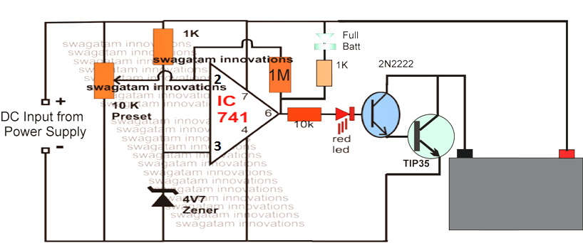
As can be found the circuit is an automatic battery charger circuit, consisting of an operational amplifier that is responsible for governing the state of the battery to identify the actual time by which it should stop charging the battery and trigger the LED indicator.
The three-stage resistive divider enables you to make reference voltage for the operational amplifier. In this manner, the battery cut-off takes place when the current drops under the half-ampere, and the circuit starts to oscillate by operating the transistor that switches current to the LED resulting in it to glow and indicate the full charge level of the battery.
Remember that the bridge rectifier for the input power supply may need to be above 10 amperes (voltage equal to or greater than 50V) therefore it is certainly not for soldering in printed circuit rather needs to be screwed to the metallic cabinet of the apparatus and hook up by crimped terminals.
The original filter capacitor could be bolted up onto the plate or could be twisted in the cabinet by using a couple of plastic seals and joined in parallel with the positive and negative terminals of the rectifier bridge. The typical switch will be of the style employed in electric coffee machines that include neon gas lamp which signals if the charger is switched on.
Seriously consider how this switch is actually attached because it is quite common to mistake the terminals and short circuit the 220V line. In case preferred, a DC ammeter may be inserted in line with the positive terminal of the output on the battery in order to visually keep track of the current of the battery.
This device could be comparable or electronic digital battery charger, despite the fact that these days it really is a lot more jazzy these digital ones. The positive terminal of the device links to the circuit as well as the negative would go to the battery (in the direction of its positive terminal).
You possibly can put a buzzer that will sounds simultaneously in conjunction with the LED triggering. This should be attached between anode of the LED and the emitter of the transistor and needs to be of the electronic piezo type, having oscillator a part of its internal circuitry.
In order to apply it just connect the battery to charge, switch on the system and push the pushbutton that will begin charging. Once the charging is accomplished, the device LED will illuminate and the unit should be switched off and the battery taken out of the terminals.
How to Set up this automatic universal battery charger circuit
Suppose you want to charge a 12V 200AH battery charger circuit. You will need to complete the following initial procedures:
Do not connect the battery as yet, first apply a 14.4V from the DC input side, and adjust the 10K preset such that the green LED just lights and the red LED just shuts off.
That's all, you are done.
Now connect the 12V 200AH battery, switch ON the input from a DC 14.4V 20 amp source and let the battery begin charging.
You will the red LED glowing while the battery is charging, and as soon as it reaches 14.4V, the red LeD shuts off and the green LED lights up indicating the full charged status of the battery
Thanks for the good work you are doing, However am trying to understand the calculations for upgrading the transistors so as to charge a a 100AH or 50AH battery using solar panel of 100w but I can’t see anywhere you have indicated how the calculations are done.
Kindly help me.
Thanks for the question. The TIP35 can handle upto 10 amps easily, so it can be used for charging 100 Ah battery and also 50 Ah battery, at a rate of 10% of the battery Ah rating.
How to limit charging current in this diagram?
You can use the DC input supply which has a current matching the battery.
Good evening sir. Does this charger circuit has trickle charge feature when the battery full voltage gets to 13v
Emejakpor, no it does not include a trickle charge facility, but you can simply add it by connecting a 220 ohm 2 watt resistor across the collector/emitter of the TIP35 transistor
Thanks remain bless very commendable my regards sir I love you keep it up
thank you very much!
pls if am charging 12v 480ah which transistor can i use
It is better to provide a current limiting resistor in series with the positive of the bat terminal (1/10% of the bat ah) can we use lm 393 in place of 741 ic . for 48v 200ah bat which transistor should be used.
yes you can use any opamp, just make sure the IC Vcc is supplied through a regulator…and use a pull up resistor for LM339 output
which is the resistance of 0.1 ΩM ..?
it was a mistake, I have removed it!
This ckt can be used or not for – 48 volt and 200 ah battery.
yes it can be used for any battery…by upgrading the transistors and the supply accordingly
The resistance of 0.1 ohmu must be placed on, but trombocytoch must be increased by 2 or 3 cm of it, in order to avoid temperature changes its heat. What it means? Nowhere in there on the I don’t see any resistance 0.1 ohmu.
Thank you for the reply, do I remain yours.
yes the current control feature is not included by mistake in the diagram, i may do the correction soon
Very useful site and blog for in the fields of electronics and electrical thank you for the exciting circuits.
welcome!!
Please, Electronics Engineer like your universal automatic battery charger. Please I have been seeing two of this circuit diagram one the LED green the anode is connected to the positive line of the battery and the same green the cathode is connected to the same battery positive. Please help me to give me the right circuit diagram to build for my own car battery charger. Am Electronics and Electrical. Taking my battery for charge all the time and is not charged well, that is why looking for your help.
Thank you for the question. The above circuit is perfect, the LEDs are correctly configured…so it will work if built correctly.