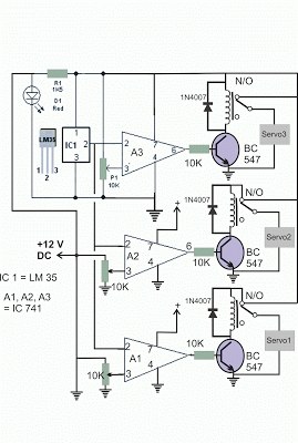
The article talks about a basic opamp structured automotive engine heat controller circuit for regulating servos in accordance with the coolant heat, the concept was wanted by Mr. John
Circuit Request
Really like your websites. Discovered a lot of circuit I am going to be constructing.
I am trying to find an easy automobile circuit that should switch on around three 12V servos, impacted by engine coolant heat range as calculated by the temp transmitting unit.
After that switching the servos off one by one as the engine warms up.
For a second time as contingent on the temperature transmitting unit. Servos could possibly be operated through relays.
Temperature Ohms 48 degrees F 7000 87 degrees F 1930 146 degrees F 560
Thanks John
How the Circuit Works
Scientific explanation of the suggested automotive engine temperature controller circuit: A1, A2, A3 are three opamps IC 741 designed as comparators, with their inverting inputs hooked up to the output of LM35 IC which is basically a precision temperature detectors microchip.
The non-inverting inputs of the three opamps are connected using 10k presets just about every for the necessary controls.
A1 preset is fine-tuned in ways that its production turns out low from the stipulated 48 degrees C, in the same way A2 and A3 presets are grouped to deliver zero voltages at the particular opamp end results in accordance with the temperatures of 87 and 146 degrees C correspondingly.
In case the above is scheduled and power is activated, all of the relays are concurrently switch ON initiating the servo1,2,3.
At this point as the engine starts out to heat and grows to the first limit of 48 degrees C, A1 relay switches OFF the Servo1, in the same manner, A2 switches of servo2 at the set 87 degrees C, as well as A3 toggles off servo3 at around 146 degrees C.

Leave a Reply