• Skip to main content
  • Skip to primary sidebar

Making Easy Circuits

Learn and build electronic circuits

You are here: Home / Car and Motorcycle Projects / Automotive Speed Limit Indicator Circuit

Automotive Speed Limit Indicator Circuit

Last Updated on February 17, 2018 by Admin Leave a Comment

In our earlier content we certainly have found out widely concerning the ICs LM2907/LM2917 which can be simply frequency to voltage converter ICs, and are preferably relevant in all such appropriate fields. Here we observe how the same chip can be utilised to create a vehicle speed limit alarm circuit.

Speedometer Image

In accordance with the described instance the IC could be utilized to make a basic speed limit switch circuit which often might be used in vehicles for detecting over-speeds and progressively alarming or stopping the vehicle from passing the set dangerous mark.

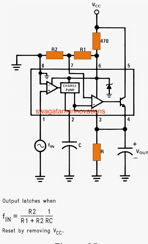
As revealed in the below diagram a single LM2917 is sufficient for designing the suggested speed limiter circuit together with a few external passive components.

Talking about the diagram, the input pin#1 obtains the signal from the wheels of the vehicle by means of a magnet and pickup coil arrangement or by means of a Hall impact sensor circuit.

You might signify this post for understanding the simple set up of the wheel and pickup coil in the presented diagram.

The feature is fairly a lot very much like the earlier spelled out speedometer circuit working:

The utilized speed info by means of pulses matching the revolving wheel count is imagined by the contrary opamp whose inverting input is referenced to ground for highest sensitivity.

The output out of this opamp is given to the subsequent that may be the charge pump stage to blame for tracking/holding/boosting the information through a gradual DC.

This work depends especially on the value of C a pin#2 of the IC.

The above information and facts are more heightened and compared by the succeeding opamp and common collector transistor phase.

The output is shut down at pin#4 of the IC via the emitter of the internal common collector transistor.

According to the formula, the speed limit alarm could be set and determined by utilizing the formula:

f(in) = R2/R1+R2 x 1/RC

Once the set limit is attained, the IC picks up it and generates a high logic at pin#4 which is equivalent to the supply voltage of the circuit.

This high logic can be utilized for appearing an alarm, deactivating the engine or for initiating further comparable preventive steps.

vehicle speed limit indicator circuit

A standard execution of the above design may be observed right here diagram. Right here the load or the speed limit warning alarm is linked at the transistor collector pin#5 output rather than pin#4 as narrated in the above spot.
The collector load configuration presents the benefit of better current acquire enabling a greater wattage device for example a relay or an alarm to be instantly utilized with the circuit.

simplespeedlimitswitchcircuit

You'll also like:

  • 1.  Cold Cranking Ampere CCA Estimator Circuit
  • 2.  Bicycle Light and Alarm Circuit
  • 3.  Simple Temperature Indicator using BC547 Transistor
  • 4.  DIY GSM Car Security Alarm Circuit
  • 5.  LED Brake Light Circuit for Cars and Motorcycles
  • 6.  How to Make a Bicycle Horn Circuit with Ringtone

About Admin

Hey friends, Thanks a bunch for stopping by this site! I am an engineer with a Bachelor of Engineering in Electronics and Telecommunication. One of my passions is gathering information from all sorts of electronics books and tutorials. I then take that information and compile it into a language that is super easy to understand. My goal is to make those complex electronics circuit concepts and technical terms much more accessible for all the new and budding electronics engineers out there. I can also design customized circuit diagrams as required by the users.
If you have any questions related to this field, please do not hesitate to drop a comment! I am always here and ready to help you out with any queries you might have. I cannot wait to hear from you!

Reader Interactions

Leave a Reply Cancel reply

Your email address will not be published. Required fields are marked *

Primary Sidebar

Categories

  • 3 Phase (4)
  • 8051 Microcontroller (1)
  • Arduino (11)
  • Audio and Amplifier (102)
  • Automation (8)
  • Battery Chargers (64)
  • Bicycle Projects (4)
  • Car and Motorcycle Projects (39)
  • Datasheets (10)
  • DIY Projects (5)
  • Electrical (15)
  • Free Energy (6)
  • Games Projects (2)
  • High Voltage (14)
  • Hobby Projects (30)
  • Household Circuits (2)
  • IC 555 Circuits (5)
  • Ignition Circuits (2)
  • Indicators (50)
  • Infrared (6)
  • Inverter Circuits (29)
  • Lights and Lamps (97)
  • Medical (8)
  • Meter and Tester Circuits (38)
  • Motor Driver (17)
  • New Circuits (56)
  • Oscillators (30)
  • Pets and Pests (5)
  • Power supply (80)
  • Protection Circuits (25)
  • PWM (9)
  • Remote Control (20)
  • Security and Alarm Circuit (48)
  • Sensors and Detectors (66)
  • Signal Processor (23)
  • Solar Controller Circuits (62)
  • SSR (3)
  • Temperature Controller (20)
  • Timer (25)
  • Transformerless (7)
  • Transmitters (12)
  • Tutorials (45)
  • UPS (2)
  • Voltage Regulators (57)
  • Water Sensor and Controller (29)
  • Home
  • Privacy Policy
  • Contact
  • Disclaimer
  • Copyright

© 2025 · Making Easy Circuits