• Skip to main content
  • Skip to primary sidebar

Making Easy Circuits

Learn and build electronic circuits

You are here: Home / Timer / Bedside Lamp Timer Circuit

Bedside Lamp Timer Circuit

Last Updated on January 10, 2018 by Admin Leave a Comment


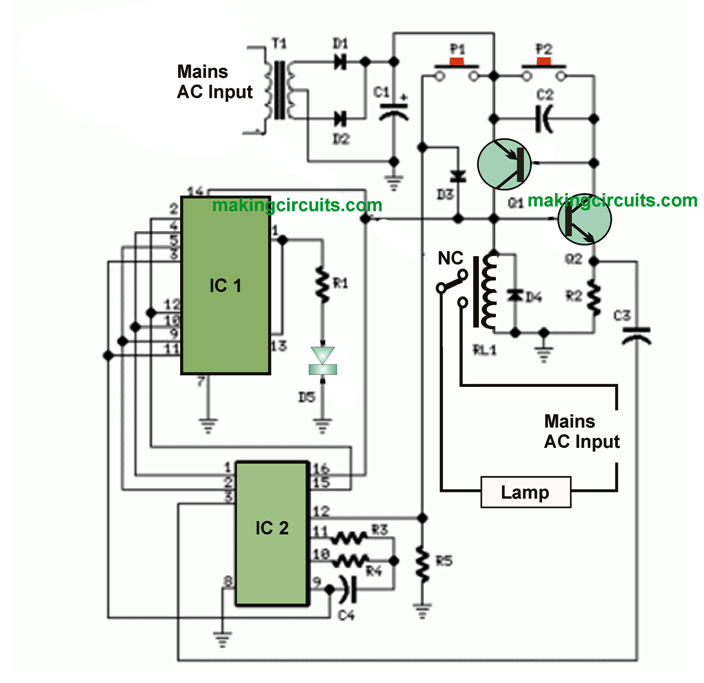
The bedside lamp timer circuit as depicted in the article is a useful energy saver as often a bedside lamp is used for reading is kept ON even when the reader is asleep this particular circuit automatically turns off after a given time T1. There are two push to on switches namely P1 and P2 connected with the bedside lamp. When P1 is pressed D5(red LED) glows for 25 minutes that is the reading time allocated. 6 minutes before the switches off the LED blinks for 2 minutes giving an alarm to the reader that his reading time is getting over. Thereafter it stops blinking for 2 minutes and after this interval this interval it again start blinking for 2 more minutes indicating the ON time has ended. If the reader wants to enhance the time of reading it is required to press P1 once again.Thus continuing the reading as per will. At any point of time the reader can turn it off by pressing P2.
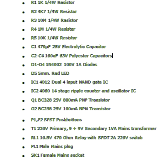
bed lamp timer circuit

Parts List


parts


Circuit operation:

Q1 and Q2 are preferably complementary in characteristic. Here in this circuit. Q1 is BC328 which is a 800mA PNP transistor and Q2 is BC238 which is a 100mANPN transistor. Q1 and Q2 are such connected that in the off state it has least drainage current. As soon as the switch P1 is pressed the relay is turned ON and IC1(4012 Dual 4 input NAND Gate) and IC2 (4060-14 Stage ripple counter and oscillator) get power. The relay power up the lamp abs IC2 gets reset as a HI appears at pin no 12. R4 and C4 determines the oscillating frequency of IC2. By changing the value of R4 and C4 time T1 can be adjusted. As soon as the pin no 3 of IC2 goes high after 30 minutes (T1) this turns off the circuit via C3.
During those 6 minutes of alarm time the LED blinks at a frequency that is provided by the oscillator IC (IC2) at pin no 9. IC1 is connected to IC2 pin 1, 2 and 15 as shown in the bedside lamp timer circuit. Two NAND gates of IC1 are parallel to boost the current to the blinker. The time can be aler altered by altering the values of R4 and C4. An optional buzzer of Piezo character can be introduced between pin 1 and 14 of IC1.
Note:

It is observed in practice that the timing changes with different brands of IC2. In particular Motorola make ICs operate faster.


You'll also like:

  • 1.  IC 4060 based 2-step Programmable Timer Circuit
  • 2.  Accurate 24 Hour Timer Circuit
  • 3.  How to Build a Aquarium Fish Feeder Timer Controller Circuit
  • 4.  How to Build a Timer Circuit with Auto Pause and Resume During Power Failures
  • 5.  Making Delay Timers using NOT gates IC 4049
  • 6.  Programmable Timer Circuit for Fish Aquarium

About Admin

Hey friends, Thanks a bunch for stopping by this site! I am an engineer with a Bachelor of Engineering in Electronics and Telecommunication. One of my passions is gathering information from all sorts of electronics books and tutorials. I then take that information and compile it into a language that is super easy to understand. My goal is to make those complex electronics circuit concepts and technical terms much more accessible for all the new and budding electronics engineers out there. I can also design customized circuit diagrams as required by the users.
If you have any questions related to this field, please do not hesitate to drop a comment! I am always here and ready to help you out with any queries you might have. I cannot wait to hear from you!

Reader Interactions

Leave a Reply Cancel reply

Your email address will not be published. Required fields are marked *

Primary Sidebar

Categories

  • 3 Phase (4)
  • 8051 Microcontroller (1)
  • Arduino (11)
  • Audio and Amplifier (102)
  • Automation (8)
  • Battery Chargers (64)
  • Bicycle Projects (4)
  • Car and Motorcycle Projects (39)
  • Datasheets (10)
  • DIY Projects (5)
  • Electrical (15)
  • Free Energy (6)
  • Games Projects (2)
  • High Voltage (14)
  • Hobby Projects (30)
  • Household Circuits (2)
  • IC 555 Circuits (5)
  • Ignition Circuits (2)
  • Indicators (50)
  • Infrared (6)
  • Inverter Circuits (29)
  • Lights and Lamps (97)
  • Medical (8)
  • Meter and Tester Circuits (38)
  • Motor Driver (17)
  • New Circuits (56)
  • Oscillators (30)
  • Pets and Pests (5)
  • Power supply (80)
  • Protection Circuits (25)
  • PWM (9)
  • Remote Control (20)
  • Security and Alarm Circuit (48)
  • Sensors and Detectors (66)
  • Signal Processor (23)
  • Solar Controller Circuits (62)
  • SSR (3)
  • Temperature Controller (20)
  • Timer (25)
  • Transformerless (7)
  • Transmitters (12)
  • Tutorials (45)
  • UPS (2)
  • Voltage Regulators (57)
  • Water Sensor and Controller (29)
  • Home
  • Privacy Policy
  • Contact
  • Disclaimer
  • Copyright

© 2025 · Making Easy Circuits