The submit addresses a straightforward two magnet BLDC controller circuit integrating a single hall sensor.
In one of the earlier articles we mentioned the simple functioning thought of BLDC motors and acquired a Hall sensor is utilized for signaling the motor's electromagnet by means of an external connected electronic circuit for preserving a constant rotating motion of the rotor.
The procedure for developing a fixed stator electromagnet and a rotating free magnetic rotor guarantees improved effectiveness to BLDC motors in comparison to the traditional brushed motors which have precisely the opposite topology thereby desire brushes for the motor operations. The utilization of brushes produces the methods fairly ineffective with regards to long life, consumption and size.
Despite the fact that, BLDC types might be the most effective motor concept, it includes one important disadvantage that it will require an external electronic circuit for performing it. However, with the arrival of modern ICs and sensitive Hall sensors this problem now appears to be quite insignificant in comparison with the high degree of performance associated with this principle.
In the existing post we have been talking about a simple and easy and fundamental control circuit for a four magnet, single hall sensor type BLDC motor. The motor operation could be recognized by talking about the following motor mechanism diagram:
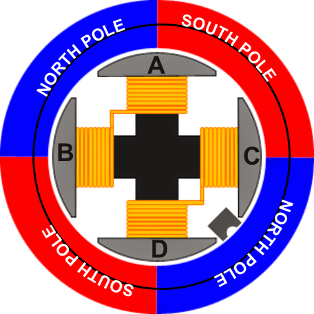
The image above demonstrates a fundamental BLDC motor arrangement owning two sets of permanent magnets across the periphery of an external rotor and two sets of central electromagnet (A,B,C,D) as the stator.
To be able to start and maintain a rotational torque often A, B or C, D electromagnets ought to be in an triggered state (never together) relying upon the positions of the north/South poles of the rotor magnet with regards to the started electromagnets.
To be accurate, let's believe the situation demonstrated in the above situation with A and B in a turned on state such that side A is energized with South pole while side B energized with North Pole.
This could certainly imply that the side A could be exerting a pulling impact over its left blue North pole and a repelling impact on its right side south pole of the stator, in the same way the side B could well be drawing the lower red south pole and repelling the upper north pole of the rotor....the whole method could possibly be then believed to be exerting a remarkable clockwise motion over the rotor mechanism.
Let's also believe that in the above circumstance the Hall sensor is in a deactivated condition since it might be a "south pole activated" Hall sensor device.
The above impact would certainly attempt to align and force the rotor such that the south locks on face to face with side B while the north pole with side A, nevertheless before this circumstance has the capacity to transpire the Hall sensor is introduced in a close proximity to the shifting upper south pole of the rotor, and when this just transits across the Hall sensor it is forced to turn on, delivering a positive signal to the hooked up control circuit which immediately replies and switches OFF electromagnets A/B, and switches ON electromagnets C/D, making certain that the clockwise moment of the rotor is one more time enforced sustaining a regular rotational torque on the rotor.
The above described switching of the electromagnets as a reaction to the Hall sensor activating signal can be very simply executed implementing the following uncomplicated BLDC control circuit idea.
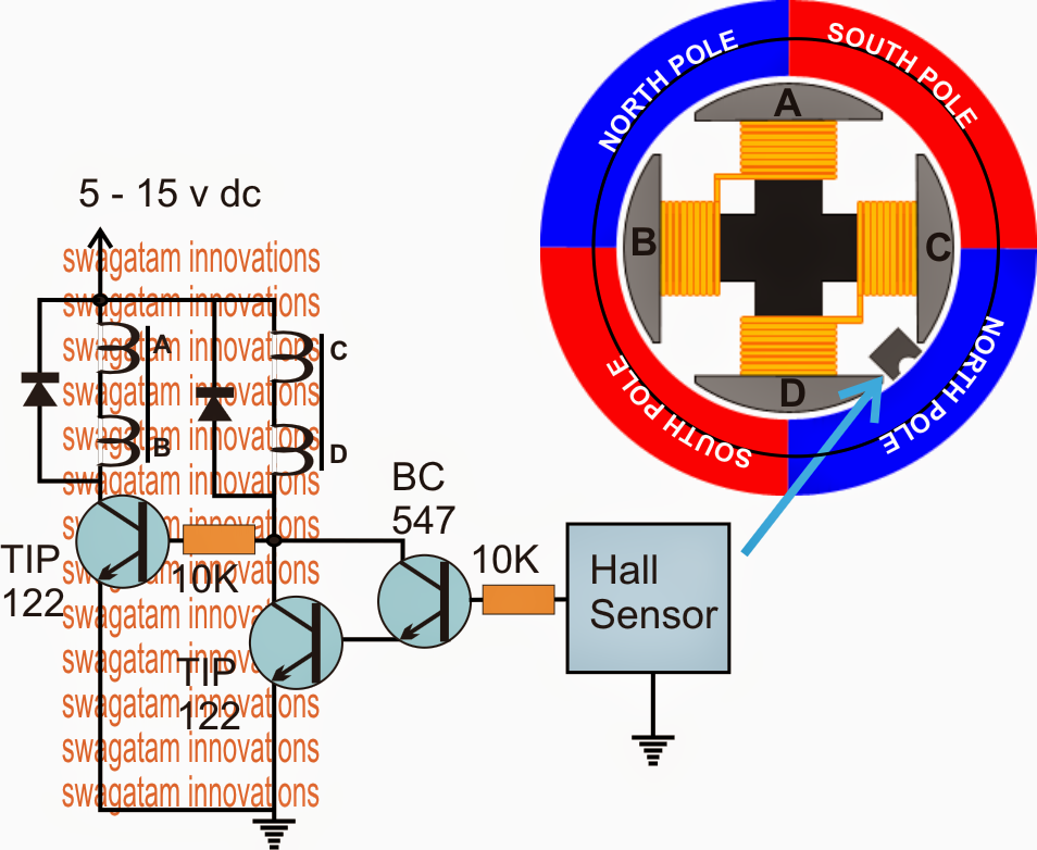
The circuit is not going to require much of an explanation since its too simple, in the course of the activate circumstances of the Hall sensor, the BC547 and the coupled TIP122 is in the same manner activated which often turns ON the related sets of electromagnets linked across their collector and positive, throughout the disconnect periods of the Hall sensor, the BC547/TIP122 pair is turned OFF, but the significant left TIP122 transistor is turned on triggering the opposite sets of electromagnet.
The condition is toggled alternately, constantly provided that power continues to be utilized maintaining the BLDC rotating with the necessary torques and momentum.
This circuit seems to “Drive” the BLDC motor but not provide any “Control”….