The Hartley oscillator is basically a frequency generator circuit where the oscillation frequency kind of hangs on what's happening in a tuned circuit. That circuit involves capacitors and inductors, so like it's just a type of LC oscillator, plain and simple.
Using a Single CMOS Gate
Now you can even use a single CMOS inverter to build one of those popular Hartley oscillators. This kind of Hartley oscillator circuit is actually much better than regular LC oscillators because you only need one winding for the coil. But that coil's got to be a center-tapped winding, right? You can check out the circuit diagram for this CMOS Hartley oscillator in the figure below.
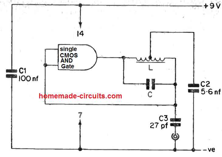
So the way the Hartley oscillator works is quite like how the Pierce oscillator does its thing, except, instead of using a crystal with a capacitively center-tapped setup, it uses a center-tapped LC stage.
Now this inductor L, it gives a DC path between the CMOS inverter's input and output and that means the circuit can run without needing a bias resistor. Pretty neat, right?
The circuit can work with frequencies from a few 100 kHz up to a max of 10 MHz. But just remember these frequencies depend on the values of L and C so you got to pick them carefully to match the frequency range you' are aiming for.
And if you want the Hartley circuit to act like a variable frequency oscillator, just make that capacitor C variable. Also keep in mind that the tapping on the coil L doesnt have to be right in the middle of the winding. So lik, the circuit can still work even if you swap out L with the primary of an I.F. transformer.
You can totally play around with the coil L by using different numbers of turns on a ferrite core and then checking out the results on a frequency meter.
In the Hartley diagram, they' have used an AND CMOS gate but you can also use a buffer CMOS gate, like the one from the IC 4050.
Hartley Oscillator Circuit with a single transistor
Now check this out: you can also make a Hartley-type oscillator circuit with a single transistor!
This single transistor oscillator circuit, which is tuned with a transformer and makes a sine wave AF, is actually a Hartley type oscillator circuit. The tuning and feedback are all done with just one center-tapped winding on the transformer. Then, the other winding of the transformer is there to act like an output coupling coil.
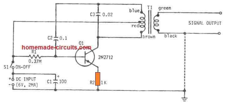
So if you wanna build this Hartley circuit, you got to get yourself a small transformer T1. This transformer is a 500 ohm to 30 ohm center-tapped kind. That means one side of the winding, the circuit winding, has around 500 ohms, and the winding on the output side has roughly 30 ohms.
The top half of the center-tapped primary winding of L1 is acting like the base-input coil while the bottom half of the primary side of L1 is acting as the collector output coil.
Capacitor C3 is the one that's responsible when it comes to tuning the oscillation on the transformer's primary side. The frequency of the Hartley circuit is basically determined by capacitor C3 and how much inductance the whole primary winding has.
Like it says in the diagram, if the C3 value is 0.02 mfd then you' are looking at a frequency of around 2 kHz. If you want to crank up the frequency, try making the C3 capacitance smaller. On the flip side if you wanna bring the frequency down, just make the C3 capacitance bigger.
To make sure the circuit oscillates nicely, the transformer winding needs to be polarized correctly, just like the transformer's specs say, usually with some color dots.
Capacitor C2 isn't really doing anything in the tuned circuit, but it's there to stop the collector DC voltage from sneaking over to the transistor's base.
The circuit gives you an amplitude of 0.8 V RMS when there' is no load attached. And it's using about 2 ma of current when you're powering it with a 6V DC supply.
Hartley Oscillator with LC Feedback
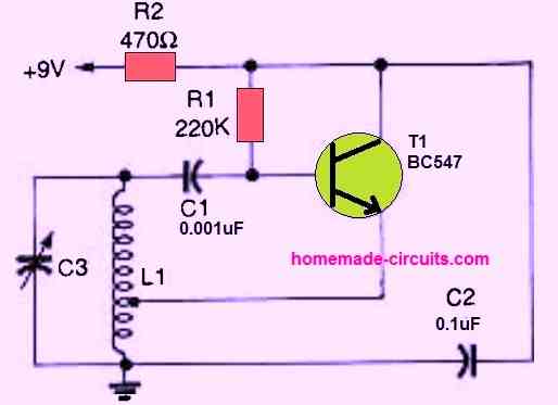
So check out, that figure up there shows a modern RF Hartley transistor oscillator circuit. The values of L1 and C3 are the ones in charge of controlling the oscillator's working frequency.
And where you put the tap on L1 usually somewhere between 1/5th and 1/4th of all the turns, that's what decides how much feedback you're gonna get.
For example this Hartley oscillator will run at 5 MHz if you set up the L/C combo like this: L1 should have 20 turns of 18 SWG enameled copper wire, wound nice and tight on a 1-inch plastic thing. And you'll want to put a tap after five turns from the bottom.
C3 should be a small adjustable capacitor maybe with a max capacitance value of 100 pF. Circuit designers really dig the Hartley oscillator 'cause it can work anywhere from the low audio range all the way up to the UHF range as long as you' have got the right L/C values
Leave a Reply