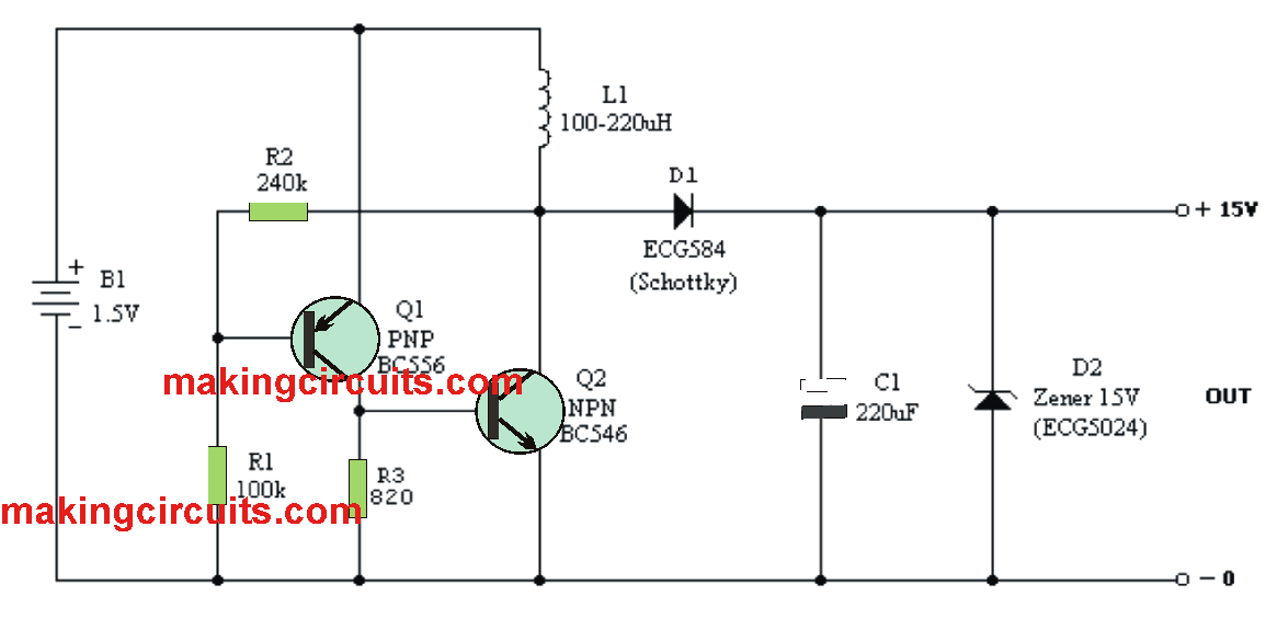
This circuit is basically a step-up DC-DC converter, which permits to acquire 15 volts of output originating from an ordinary 1.5 volt (B1) battery without necessitating the use transformers or customized integrated circuits. The very center of the circuit is undoubtedly an oscillator, created close to a couple of complementary transistors (Q1 and Q2), that regulates a coil (L1).
As soon as B1 is toggled ON, current runs by means of R2 and R1 at first, leading to Q1 and Q2 to saturate and conduct. Consequently, L1 is traversed by a current which steadily magnetizes its core until it finally saturates it. At this point, the flow of current stops internally and the magnetic field associated with the coil drops, producing a counter electromotive force (fcem) which inversely polarizes the base of Q1. Because of this, Q1 and Q2 ceases to conduct. The process now starts repeating rapidly and indefinitely.
The energy of the fcem created by L1 is rectified by a Schottky diode (D1) and stored in an electrolytic capacitor (C1) in the form of DC voltage Due to the fact that this voltage is fairly high, more than 20V, any output voltage under this value could be very easily attained by using a zener diode or a three-terminal regulator. In this instance a 15V zener (D2) is employed, nevertheless an additional reference voltage can be employed according to the specific demands.

Koga73 says
Great design! How could you integrate a pot to vary the frequency (and thus the voltage)?