This automobile battery warmer circuit's primary goal is to ensure that the battery may be effectively recharged and discharged while operating at extremely low temperatures.
Circuit Objective
My intention entails overseeing the operation of a silicone heat pad operating at 12 volts direct current (VDC) and 30 watts, with the aim of heating an automobile battery.
In Finland, where temperatures often plummet below zero degrees Celsius, it is recommended to preheat lead-acid batteries.
During frigid conditions, the battery's ability to absorb charging current diminishes compared to warmer environments, such as twenty degrees Celsius.
The initial concept involves utilizing the battery terminals to supply power directly to the temperature sensor circuit, while an external alternating current (AC) battery charger is employed to provide power for heating the pad.
However, a crucial inquiry arises: does a relay afford adequate galvanic isolation?
The strategy involves employing the heater during vehicular motion, relying on the alternator to furnish power to the heating pad.
Additionally, contemplation is given to a straightforward circuit design that activates the heater solely when the voltage attains a specific, preferably adjustable, threshold, such as 13.8 volts.
In this configuration, activation of the heating pad would only ensue under one of two circumstances: either the engine was operational with the alternator engaged, or the external battery charger was connected and operational.
Circuit Description
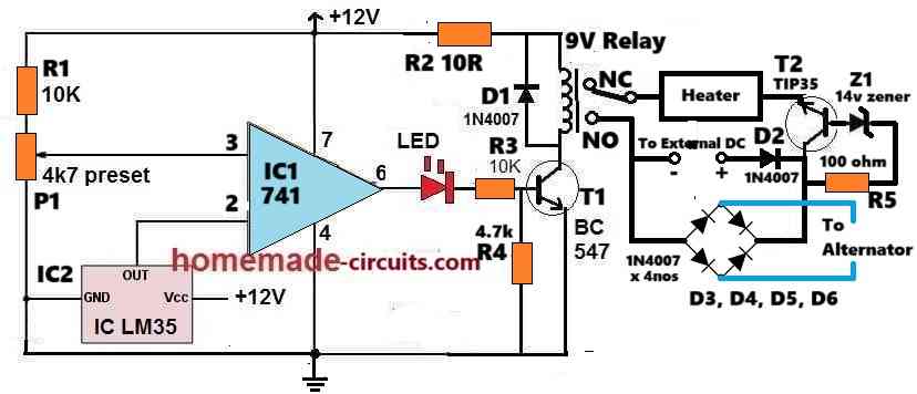
The following factors can help you understand how the vehicle battery warmer circuit diagram above operates:
The IC 741, IC1, is set up to function as a comparator. As a result, IC1 examines the voltage across pins 2 and 3. Its output will remain high as long as its pin #2 potential is lower than the pin #3 potential, and vice versa.
An IC used for temperature detection in automobile batteries is the IC2 LM35. Its output voltage (OUT pin) rises by 10 mV for every degree Celsius that the surrounding air temperature rises.
This LM35 IC output is connected to the IC741's inverting input pin #2.
A preset P1 is connected to the non-inverting input pin of IC 741, fixing or setting the value of the reference voltage at pin #3 of the IC.
Once the temperature of the battery and the ambient are both warm enough, the LM35 output at pin #2 of 741 is noticeably greater.
The P1 setting is chosen so that, in a situation when the ambient temperature is moderate and the battery doesn't require external warming, the pin#3 voltage of IC 741 remains marginally below the potential at pin#2, which is provided by the LM35 output.
Because pin#3's voltage is somewhat lower than pin#2's in the aforementioned scenario, IC1's output at pin#6 stays at low logic, or 0V. As a result, transistor T1 remains in the off state, leaving the relay contacts in the N/C position.
The heater remains unplugged and switched off while it is in the N/C setting. This implies that the heater will stay off as long as the surrounding air is heated.
Let us now assume that the outside temperature begins to decrease and falls below the set threshold.
In this case, the LM35 output goes down as well until the 741 IC pin #2 voltage falls beneath the pin #3 reference voltage value.
As a result, IC 741's output pin #6 immediately becomes high.
Both the heater and the relay turn on at that moment.
The battery is currently being heated by the heater until the temperature reaches a certain value, at which point the relay turns off.
The heater keeps going through the aforementioned ON/OFF cycle, making sure that the battery temperature is consistently warm and in ideal condition.
Power Supply
The car's alternator voltage or an external AC to DC adapter are the two sources of power for the heater.
The zener diode Z1 and transistor T2 work together to guarantee that the heater can only run when the supply voltage from the alternator or adaptor is at least 14V.
Parts List
| Component | Specification |
|---|---|
| Resistors (10 kΩ) | 10 kΩ, 1/4 watt, 5% CFR (2 pieces) |
| Resistor (10 Ω) | 10 Ω, 1/4 watt, 5% CFR (1 piece) |
| Resistor (4.7 kΩ) | 4.7 kΩ, 1/4 watt, 5% CFR (1 piece) |
| Resistor (100 Ω) | 100 Ω, 1/4 watt, 5% CFR (1 piece) |
| Preset (4.7 kΩ) | 4.7 kΩ Preset Potentiometer (1 piece) |
| Transistor (BC547) | BC547 (1 piece) |
| Transistor (TIP35) | TIP35 (1 piece) |
| IC (LM35) | LM35 Temperature Sensor IC (1 piece) |
| IC (IIC 741) | IC 741, Operational Amplifier (1 piece) |
| LED (5mm, 20mA) | 5mm, 20 mA LED (1 piece) |
| Zener Diode (14V) | Zener Diode 14V, 1 watt (1 piece) |
| Diodes (1N4007) | 1N4007 Diodes (2 pieces) |
| Diodes (1N5402) | 1N5402 Diodes (4 pieces) |
| Relay (9V, SPDT) | 9V SPDT Relay (1 piece) |
| Heater Pad (12V, 30W) | 12V, 30W Heater Pad (1 piece) |
Leave a Reply