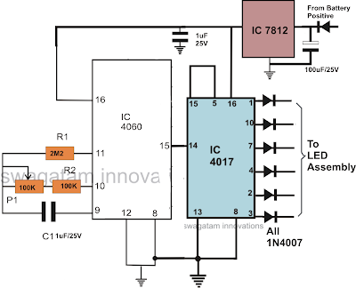
The submit addresses the development chasing car tail light circuit making use of high bright 1 watt amber LEDs.
Including higher wattage LEDs will require individual transistor buffers across the 6 outputs from the IC, it's in fact very simple to put into practice.
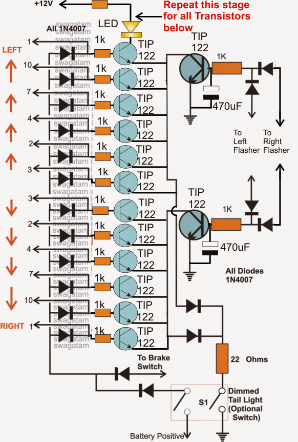
I'll attempt to clarify the connections verbally, despite the fact that I am additionally considering modifying an appropriate diagram for this specific application, I may do it within a few days....in the meantime you could attempt carrying out the following mods in the above circuit:
Utilize TIP122 for the buffer transistors.
Hook up the bases of the 6 transistors to the specific outputs of the IC 4017 by means of the mentioned diodes. Make certain the base include individual series 1k resistors
The LEDs will have to be connected across the transistor collectors and the positive, the LEDs as well should have their very own series decreasing resistor
The LED resistors could possibly be determined employing the following formula:
R = (Us - LEDfwd)/I
where Us is the supply voltage,
LEDfwd is the optimum glow voltage of the LED or the forward voltage drop spec.
I is the optimum current for the LED as stipulated in its datasheet.
That's all..... right now your circuit is prepared and could well be effective at managing any kind of high watt LEd in the range....


I dont have much knowledge of electronics. I can only see one led. where are the other connected too??
You must repeat that LED stage across the collectors of all the TIP122 transistors…