The purpose of the discussed triac based day night activated switch circuit is to automatically switch OFF a given electrical appliances and peripherals during day light and vice versa, this could be a lamp, an alarm, etc.
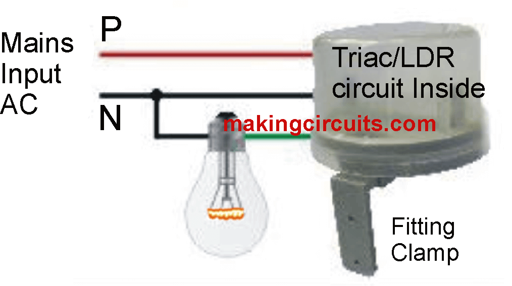
Generally speaking, this is a type of photoelectric relay which is driven directly through the home's mains electrical system, with no need for any kind of mechanized device like relay or other component.
This day night switch circuit using triac and LDR is extremely straightforward, therefore its inexpensive and simple to build, only there exists one particular drawback, it is not flexible and is not going to enable electronic adjustments to drive or modify the switch. That, by the way, is not a mechanical switch, rather an SCR or triac.
Photoelectric relay cell
Interconnection of a photoelectric relay cell
Photoelectric relays
There are numerous remedies developed to automatically switch off the lamps as soon as it's dark. Generally we require a DC power supply and an electromechanical relay, however in case you come up with a circuit which can be directly coupled to the AC power supply, the quantity of components necessary is usually minimized down and that is exactly what reveals in this project displayed below.
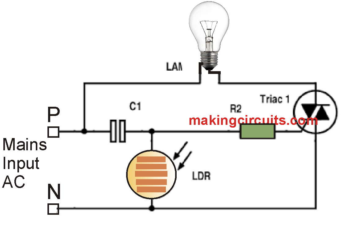
The key component of the day night triggered triac switch circuit is a LDR photoresistor of sensitive resistance, resistance in Quebec may differ its resistance According to the strength of the light it obtains, it possesses a resistance of 200 ohms at nighttime and during daylight a few thousand Ohms.
The capacitor C1 is a voltage divider for delivering the photosensitive LDR and the triac gate.
In Normal light, voltage declines as LDR resistance diminishes, however, at night, resistance to photoresistor gets higher, causing improved triac activation current, operating and lights.
Parts List
C1 = 105/400V PPC capacitor
R2 = 1K, 1/2 watt
LDR = high sensitive type
Triac = BT136
the design can’t be accepted by engineers. ldr can not be operating directly from 220v
There is a series capacitor with the AC mains, so no issues at all.
Can you explain why this works, for defense purpose, thank you for answering
This is a very crude circuit and I won’t recommend it for defense applications.
During day time, the LDR grounds all the supply, and prevents the gate voltage to the triac and therefore the triac and the lamp remains switched OFF….at night the LDR resistance becomes high enough, and the current from the 105 capacitor is able to reach the triac gate and turn it ON.
this circuit…are work led bulb….im make this circuit but..1k resistane verry heat..
use 2 watt wire wound type
is it possible to put a variable resistor and what value it should be ?
Sir, there are various remarks i.e. results have received from the hobbyists who are assembled this circuits. My request is there i.e. after receiving the results, Admin. has suggested few changes like value of resistance / lDR etc. So my suggestion is that , after proper checking and sufficient time over of particular circuit, then this may be published. if my suggestion is found proper then please do the needful. Thanks.
? 240 volts or 100 volts supply ?
both should work….
Light is working, But in LDR shows sparking some times. why?
use a bigger LDR, t is happening due to current in surge from the capacitor
I tried this circuit but it didn’t work. R1 heats up within no time.
try 4k7/ 5 watt for R2 and select an LDR which shows around 1K resistance at ambient day light
Le fonctionnement automatique du circuit est difficile à croire. Étant donné que le triac ressemble à un interrupteur électronique (irréversible ) c’est à dire qu’une fois amorcé il persiste en état de conduction même si le courant de la gâchette est coupé. Vu cette caractéristique propre au triac , la commande automatique à travers un tel composant s’avère non convenable . Car la gâchette recevant l’impulsion suffisante imposée par la LDR fait déclencher le triac puis redevient insensible à toute variation ohmique de la photorésistance. En résultat l’ampoule s’allume et le système électrique reste activé indépendamment de la quantité lumineuse incidente jour et nuit sur la LDR , à moins que le triac soit isolé du secteur pour se remettre hors service . Il y a lieu donc de modifier la commande automatique de ce circuit au biais d’une alternative basée par exemple sur un MOSFET ou un BJT de puissance.
Les triacis étant connectés à une alimentation en courant alternatif, ils ne verrouillent jamais, les triacs ne verrouillent que lorsque l’alimentation est en courant continu pur.
This is wrong:
According to the strength of the light it obtains, it possesses a resistance of 200 ohms at nighttime and during daylight a few thousand Ohms.
Should be:
According to the strength of the light it has a resistance of a few thousand Ohms at night and 500 ohms during daylight
The resistance of the LDR will not go low enough to turn off the BT136
It seems you have no knowledge of LDRs. The dark resistance of an LDR can be as high as 2 megohm and higher
Have you worked out how much current will be passed by the 1u capacitor, through the LDR when it is illuminated?
I expect the LDR to blow up.
Delete the above.
The current will flow through the 1k and BT136
I got it from this website
http://www.schemas-electroniques.tk/2016/01/schema-electrique-alimente-directement.html