This article explains a simple automatic door locking system that works when day turns into night. This clever setup is made to automatically unlock a kennel door in the morning so the dogs can go outside, and then lock it again when it gets dark.
The idea for this project came from a loyal reader of this blog, Mr. Adams, who shared his thoughts and needs for the design.
Design Request and Specifications
I am working on a circuit that will power a linear actuator.
To make this happen I created a system that changes the straight movement from the actuator into a turning motion. When the actuator pushes, a 18mm linkage turns 90 degrees which then moves a latch bar to lock the dog door.
The main goal is to let the dogs go out freely during the day while making sure the door is locked tight at night. It’s important that the system only works once to prevent the linear actuator from overheating.
The circuit is set up to turn on one relay during the day and another at night, which will manage the locking and unlocking of the dog door by activating a vehicle door solenoid.
Circuit Description
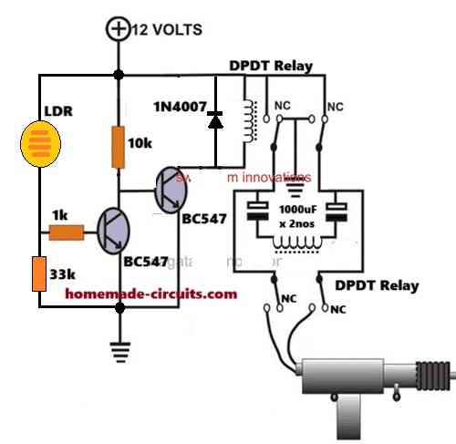
The detailed circuit diagram showing how the automatic door lock system works, which turns on based on whether it’s light or dark outside, is shown in the next figure.
To understand how this circuit functions, here are some important points:
During the day the Light Dependent Resistor (LDR) has a low resistance, which makes the left BC547 transistor turn ON. This causes the base of the right BC547 transistor to be grounded, putting it in an OFF state.
Because of this setup, the upper Double Pole Double Throw (DPDT) relay stays OFF, with its contacts at the Normally Closed (N/C) position.
With the upper DPDT relay's contacts in the N/C position, the lower relay also remains OFF, keeping its contacts at the N/C position too.
Since the vehicle solenoid is linked to the Normally Open (N/O) contacts of the lower relay, it stays inactive as well.
In this OFF state, the push-pull solenoid is set to be retracted, meaning its shaft is pulled back inside.
This retracted position allows the door lock (latch) to stay open.
So during the day the whole circuit is turned off, which keeps the kennel door spindle unlocked.
As night falls and darkness starts to cover everything, the resistance of the Light Dependent Resistor (LDR) goes up. This increase in resistance means that the voltage can't get to the base of the left-side BC547 transistor, which causes it to turn off.
When the left-side BC547 turns off, the right-side BC547 gets activated by the 10k biasing resistor, which then turns on the upper Double Pole Double Throw (DPDT) relay.
Once the upper relay is activated, its contacts switch to the Normally Open (N/O) position, changing the voltage at those contacts.
At this point, two important things happen at the same time.
The changed voltage at the N/O contacts of the upper relay sends a quick power supply to the coil of the lower DPDT relay.
This quick power makes the lower relay turn on, causing its contacts to move to the N/O position.
Since the solenoid latch is connected to these N/O contacts of the lower relay it gets the power it needs, which makes it extend its shaft forcefully.
This action locks the door by engaging the door lock spindle.
However it's important to remember that the lower relay only stays on for a very short time, usually just a second or two, until the two 1000uF capacitors are fully charged. After they charge up, the lower relay quickly turns off, going back to its Normally Closed (N/C) contacts which cuts off the power to the solenoid. This is really important because keeping the power on for too long could overheat the solenoid and damage its motor winding.
So during the night, the kennel door is locked up tight. When morning comes, everything starts over, but in the opposite way. As the sun rises the top relay turns off, which makes its contacts go back to being closed.
This change flips the polarity for the lower relay and the solenoid giving the solenoid a quick burst of power with the opposite polarity. Because of this switch in the electrical flow to the solenoid wires, the motor spins the other way, pulling its shaft back inside. This whole process makes the kennel door unlock right away.
Parts List
| Component | Specification | Quantity |
|---|---|---|
| Resistor | 33k, 1k, 10k (1 each) | 3 |
| LDR | 1 | |
| Transistor | BC547 | 2 |
| Capacitor | 1000uF / 25V | 2 |
| Capacitor (additional) | 1000uF (parallel to relay coil) | 1 |
| DPDT Relay | 2 | |
| Vehicle Door Solenoid | 12V | 1 |
This wraps up our talk about the automatic door lock circuit that works when day turns into night. This cool system is made to keep a kennel door locked tight at night and unlock it easily during the day.
The ideas behind this locking system are flexible and can be used for many other things besides just kennels.
If you have any questions or are unsure about anything related to this topic, feel free to drop a comment below, and the author will get back to you quickly.
Leave a Reply