• Skip to main content
  • Skip to primary sidebar

Making Easy Circuits

Learn and build electronic circuits

You are here: Home / Audio and Amplifier / How to Build a DIY Contact MIC Circuit

How to Build a DIY Contact MIC Circuit

Last Updated on February 17, 2018 by Admin 2 Comments

Contact mics enable you to feel uncommon sounds when connected to numerous surfaces.It also Generate sound when voltage is used on it.With the guide of a fundamental Pre-amp circuit it may also serve to Electrify an Acoustic Guitar, where amplification is essential.

DIY2Bcontact2BMIC2Bcircuit
A piezoelectric disk produces a voltage when deformed. Piezo elements are useful when needing to identify vibration or a knock. You can utilize these for tap or knock sensors quite conveniently by studying the voltage on the output. They are able to as well serve for a small audio transducer for example a Buzzer.
The trick is the preamp - a simple circuit accustomed to match the piezo’s signal.The derived piezo/preamp combo can be utilized for electrifying an acoustic guitar.
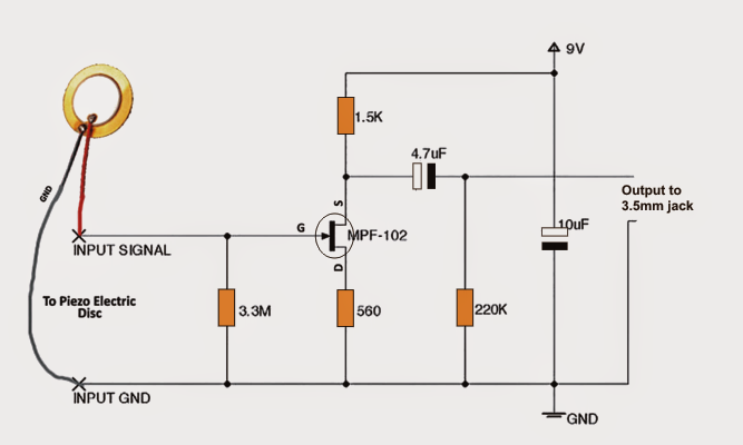
Circuit Explanation
The battery offers +9 volts which can be linked to the source of the JFET device, MPF-102. This voltage is attached to the source by means of source resistor 1.5K.
One terminal of this amplifier is well-known to both the input and output signals. This terminal is the JFET drain terminal. Because of this, we occasionally call this amplifier circuit a "common drain circuit”.The Drain resistor 220k is linked to the source to the battery's ground terminal.
The main Element utilized in the circuit is the MPF-102 Transistor. Under no-signal situations, bias voltage leads to the JFET source to obtain a very small current. This current sets the source voltage at a point halfway between the Supply and ground.This is the suggested bias setting for most small-signal or analog audio amplifiers.It permits the maximum signal before distortion.
The signal penetrates the amplifier by way of gate resistor 3.3M. The voltage drop across 3.3M is the input signal at the JFET gate. This signal is an AC voltage. The signal enters JFET,which is a amplifying device.The variance between the source and the gate sets the voltage drop across resistor 560 Ω. Typically, the bias voltage across resistor 560 Ω carries the JFET channel at a medium resistance value. The bias voltage is a DC voltage. When we use a signal, the input signal differs the negative bias voltage across resistor 560 Ω.
The different gate signal brings about the JFET's to differ. For that reason, generally current transmits through the JFET. The source resistor 1.5K transforms the current variations to voltage variations. Considering that the input signal handles the channel width.That is, a small signal manages a large signal. In our situation, the JFET gate voltage handles the JFET source current. This result’s in Amplification.
The output signal seems between the Source and ground. Capacitor 4.7uF blocks the DC voltages in the circuit, but transmits the amplified AC signal.The gate is much more harmful than the ground terminal. Now the output is developed across the Source and ground. But we've linked the Source to Supply. Then the Source is a lot more positive than the ground terminal. With the gate negative and the Source positive, This output signal simply leaves the amplifier by means of capacitor 4.7uF and shows up across resistor 220k. This Capacitor obstructs DC and moves only.
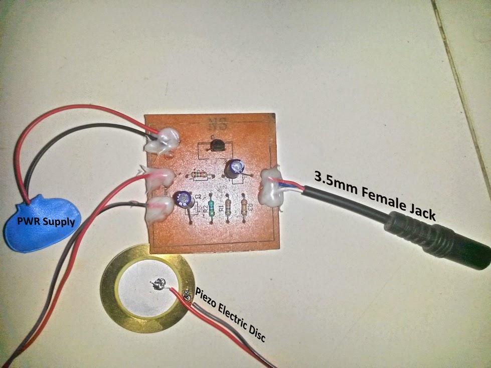
PCB Design for the above described DIY contact MIC circuit

PCBDesign
Following are the images of the DIY contact mic prototype.

BackPCBView

FrontPCBView

You'll also like:

  • 1.  70 Watt High Efficiency Power Amplifier Circuit Using IC TDA1562
  • 2.  Simple Home Theater Circuit Explained
  • 3.  How to Make a 3.7 V Class-D Speaker Amplifier for Differential Analog Input
  • 4.  How to Make a Simple Musical Greeting Card
  • 5.  Microphone Mixer Circuit
  • 6.  IC SN76477 based Enhanced Machine Gun (MG) Sound Generator Circuit

About Admin

Hey friends, Thanks a bunch for stopping by this site! I am an engineer with a Bachelor of Engineering in Electronics and Telecommunication. One of my passions is gathering information from all sorts of electronics books and tutorials. I then take that information and compile it into a language that is super easy to understand. My goal is to make those complex electronics circuit concepts and technical terms much more accessible for all the new and budding electronics engineers out there. I can also design customized circuit diagrams as required by the users.
If you have any questions related to this field, please do not hesitate to drop a comment! I am always here and ready to help you out with any queries you might have. I cannot wait to hear from you!

Reader Interactions

Comments

  1. Renault says

    September 10, 2017 at 11:39 pm

    Hi, I am trying to use a J113 JFET as a direct replacement in this circuit. I can’t seem to get it to work. Any ideas? Or can you recommend any other substitute FETs?

    Thanks

    Reply
    • admin says

      September 11, 2017 at 9:51 pm

      Hi, actually the number of the shown jfet is not at all critical, so I am not sure why your version may not be working, you can refer to the datasheet of the shown jfet number and check whether your version is missing something from the original one or not…by comparing the main features and specs from their respective datasheets you should be able to figure out the most favorable alternative….hopefully.

      Reply

Leave a Reply Cancel reply

Your email address will not be published. Required fields are marked *

Make this DIY Contact MIC Circuit

Last Updated on November 16, 2024 by Admin Leave a Comment

Contact mics can be used to sense unusual sounds when attached to various surfaces.It also Produce sound when voltage is applied to it.With the help of a basic Pre-amp circuit it can also be used to Electrify an Acoustic Guitar, where amplification is a must.

Written and Submitted by: Ajay Dusa

Piezoelectric Disc as the Sensor

A piezoelectric disk generates a voltage when deformed. Piezo elements come in handy when you need to detect vibration or a knock. You can use these for tap or knock sensors pretty easily by reading the voltage on the output. They can also be used for a very small audio transducer such as a Buzzer.

The trick is the preamp – a basic circuit used to match the piezo’s signal.

The resulting piezo/preamp combo can be used for electrifying an acoustic guitar.

Circuit Diagram

DIYcontactMICcircuit 1

Circuit Operation

The battery supplies +9 volts which is connected to the source of the JFET device, MPF-102. This voltage is connected to the source through source resistor 1.5K.

One terminal of this amplifier is common to both the input and output signals. This terminal is the JFET drain terminal.

For this reason, we sometimes call this amplifier circuit a "common drain circuit”.The Drain resistor 220k is connected to the source to the battery's ground terminal.

Using MPF-120

The main Element used in the circuit is the MPF-102 Transistor.

Under no-signal conditions, bias voltage causes the JFET source to draw a very small current. This current sets the source voltage at a point halfway between the Supply and ground.

This is the recommended bias setting for most small-signal or analog audio amplifiers.It allows the maximum signal before distortion.

The signal enters the amplifier through gate resistor 3.3M. The voltage drop across 3.3M is the input signal at the JFET gate. This signal is an AC voltage.

How JFET Works

The signal enters JFET,which is a amplifying device.The difference between the source and the gate sets the voltage drop across resistor 560 Ω.

Normally, the bias voltage across resistor 560 Ω holds the JFET channel at a medium resistance value. The bias voltage is a DC voltage. When we apply a signal, the input signal varies the negative bias voltage across resistor 560 Ω.

The varying gate signal causes the JFET's to vary. For this reason, more or less current passes through the JFET.

The source resistor 1.5K converts the current variations to voltage variations. Since the input signal controls the channel width.That is, a small signal controls a large signal. In our case, the JFET gate voltage controls the JFET source current. This result’s in Amplification.

The output signal appears between the Source and ground. Capacitor 4.7uF blocks the DC voltages in the circuit, but passes the amplified AC signal.

The gate is more negative than the ground terminal. Now the output comes out across the Source and ground. But we've connected the Source to Supply.

Then the Source is more positive than the ground terminal. With the gate negative and the Source positive, This output signal exits the amplifier through capacitor 4.7uF and appears across resistor 220k. This Capacitor blocks DC and passes only.

PCB Design for the above explained DIY contact MIC circuit

PCB Design 724x1024 1

Following are the images of the DIY contact mic prototype, built and submitted by Mr.Ajay Dusa

Back PCB View 1
Front PCB View 1

You'll also like:

  • 1.  5 Band Graphic Equalizer Circuit
  • 2.  FET Amplifier Circuits
  • 3.  Designing a MOSFET Power Amplifier Circuit
  • 4.  Buzzer Circuit Using a Transistor and Piezo Element
  • 5.  PWM Amplifier Circuit
  • 6.  DIY Guitar Jammer Circuit: Mix Tracks and Play Like a Pro

About Admin

Hey friends, Thanks a bunch for stopping by this site! I am an engineer with a Bachelor of Engineering in Electronics and Telecommunication. One of my passions is gathering information from all sorts of electronics books and tutorials. I then take that information and compile it into a language that is super easy to understand. My goal is to make those complex electronics circuit concepts and technical terms much more accessible for all the new and budding electronics engineers out there. I can also design customized circuit diagrams as required by the users.
If you have any questions related to this field, please do not hesitate to drop a comment! I am always here and ready to help you out with any queries you might have. I cannot wait to hear from you!

Reader Interactions

Leave a Reply Cancel reply

Your email address will not be published. Required fields are marked *

Primary Sidebar

Categories

  • 3 Phase (4)
  • 8051 Microcontroller (1)
  • Arduino (11)
  • Audio and Amplifier (102)
  • Automation (8)
  • Battery Chargers (64)
  • Bicycle Projects (4)
  • Car and Motorcycle Projects (39)
  • Datasheets (10)
  • DIY Projects (5)
  • Electrical (15)
  • Free Energy (6)
  • Games Projects (2)
  • High Voltage (14)
  • Hobby Projects (30)
  • Household Circuits (2)
  • IC 555 Circuits (5)
  • Ignition Circuits (2)
  • Indicators (50)
  • Infrared (6)
  • Inverter Circuits (29)
  • Lights and Lamps (97)
  • Medical (8)
  • Meter and Tester Circuits (38)
  • Motor Driver (17)
  • New Circuits (56)
  • Oscillators (30)
  • Pets and Pests (5)
  • Power supply (80)
  • Protection Circuits (25)
  • PWM (9)
  • Remote Control (20)
  • Security and Alarm Circuit (48)
  • Sensors and Detectors (66)
  • Signal Processor (23)
  • Solar Controller Circuits (62)
  • SSR (3)
  • Temperature Controller (20)
  • Timer (25)
  • Transformerless (7)
  • Transmitters (12)
  • Tutorials (45)
  • UPS (2)
  • Voltage Regulators (57)
  • Water Sensor and Controller (29)
  • Home
  • Privacy Policy
  • Contact
  • Disclaimer
  • Copyright

© 2025 · Making Easy Circuits