• Skip to main content
  • Skip to primary sidebar

Making Easy Circuits

Learn and build electronic circuits

You are here: Home / Audio and Amplifier / Door Buzzer Circuit

Door Buzzer Circuit

Last Updated on June 26, 2020 by Admin Leave a Comment

This unit is actually a two tone door buzzer of the form that generates a basic tone for around one second, accompanied by a tone of lower pitch.

The result resembles an established two tone doorbell. The buzzer tone is developed through IC2 which is generally an LM380N audio power amplifier.

Door buzzer circuit is designed to oscillate through the use of positive feedback amongst its output and non inverting input; and also the frequency of oscillation is dictated through the values of R6, R8, and C3.

fig1 28

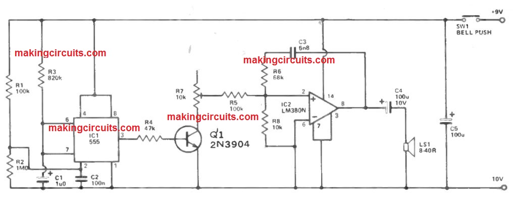
The desired values provide an functioning frequency of around 500Hz. The output from IC2 is given to a loudspeaker through DC stopping capacitor C4, and an output power of almost 1 watt RMS is acquired utilizing an 8 ohm speaker.

This drops to only around 200 mW RMS having a 40 ohm speaker, even though this would continue to supply sufficient volume for many circumstances.

The two tone result is attained through the inclusion of IC1 and its connected elements. This is a 555 IC linked within the monostable mode, and it constitutes a positive output pulse of just below one second in timeframe (fixed by R3 and C1) when a negative trigger pulse is placed on its pin 2.

This type of pulse is developed at turn on, considering C2 will certainly at first be uncharged and may acquire pin 2 of IC1 to the negative supply potential.

C2 quickly charges by means of R1 though, in order that the trigger input is easily considered positive, and may not continue to be negative at the end of the output pulse (this might possess the a result of stretching the output pulse).

When power is taken off the door buzzer circuit, R2 quickly discharges C2 so the monostable is activated once the device is controlled yet again.

Q1 is biased hard into conduction through the output pulse through la, and it as a result successfully links the series resistance of R5 and R7 in parallel with R8.

This raises the working oscillator frequency by an amount which is governed through R5. At the finish of the pulse via IC1, the oscillator functions at its standard, lower frequency, providing the specified two tone result.

R5 is modified to provide two tones providing a pleasing impact. The current usage of the door buzzer circuit differs from approximately 100mA having an 8 ohm speaker down to around 40mA using a 40 ohm type.

You'll also like:

  • 1.  How to make a Simple Music Box Circuit
  • 2.  Class B and Class AB Amplifier Circuits
  • 3.  Audio Limiter Circuit
  • 4.  15 Watt Stereo Amplifier Circuit
  • 5.  Music Stroboscope Circuit
  • 6.  DIY Guitar Jammer Circuit: Mix Tracks and Play Like a Pro

About Admin

Hey friends, Thanks a bunch for stopping by this site! I am an engineer with a Bachelor of Engineering in Electronics and Telecommunication. One of my passions is gathering information from all sorts of electronics books and tutorials. I then take that information and compile it into a language that is super easy to understand. My goal is to make those complex electronics circuit concepts and technical terms much more accessible for all the new and budding electronics engineers out there. I can also design customized circuit diagrams as required by the users.
If you have any questions related to this field, please do not hesitate to drop a comment! I am always here and ready to help you out with any queries you might have. I cannot wait to hear from you!

Reader Interactions

Leave a Reply Cancel reply

Your email address will not be published. Required fields are marked *

Primary Sidebar

Categories

  • 3 Phase (4)
  • 8051 Microcontroller (1)
  • Arduino (11)
  • Audio and Amplifier (102)
  • Automation (8)
  • Battery Chargers (64)
  • Bicycle Projects (4)
  • Car and Motorcycle Projects (39)
  • Datasheets (10)
  • DIY Projects (5)
  • Electrical (15)
  • Free Energy (6)
  • Games Projects (2)
  • High Voltage (14)
  • Hobby Projects (30)
  • Household Circuits (2)
  • IC 555 Circuits (4)
  • Ignition Circuits (2)
  • Indicators (50)
  • Infrared (6)
  • Inverter Circuits (29)
  • Lights and Lamps (97)
  • Medical (8)
  • Meter and Tester Circuits (38)
  • Motor Driver (17)
  • New Circuits (56)
  • Oscillators (30)
  • Pets and Pests (5)
  • Power supply (81)
  • Protection Circuits (25)
  • PWM (8)
  • Remote Control (20)
  • Security and Alarm Circuit (48)
  • Sensors and Detectors (66)
  • Signal Processor (23)
  • Solar Controller Circuits (61)
  • SSR (3)
  • Temperature Controller (20)
  • Timer (25)
  • Transformerless (7)
  • Transmitters (12)
  • Tutorials (45)
  • UPS (2)
  • Voltage Regulators (57)
  • Water Sensor and Controller (29)
  • Home
  • Privacy Policy
  • Contact
  • Disclaimer
  • Copyright

© 2025 · Making Easy Circuits