This electronic dice circuit constitutes a true dice display simply using only two ICs a 74132 and a 7495. The 7495 is a 4 bit parallel access shift register.
It could possibly work like a shift register or be parallel (broadside) loaded at inputs A-D. Control of these two functions can be a mode control input.
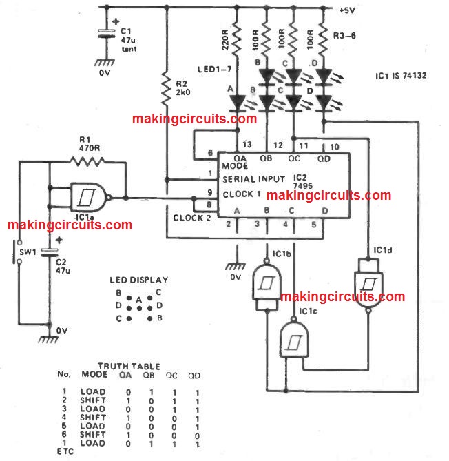
Once the mode is high data is loaded in to Qa-Qd through inputs A-D on the subsequent negative going clock edge.
If the mode is low data is moved on Qa-Qd on the next negative going clock edge.
By hooking up the mode control to Qa in order that the register alternates amongst load and shift and generating the input word a function of the present output word, which includes easy logic, the register could be designed to perform a count which will drive LEDs in a dice display.
Be aware LEDs are usually lighted when outputs are low. IC1 a is linked as a standard Schmitt oscillator supplying clock pulses to the register SW1 prevents the oscillator and stops the counting.
On turn on the register may begin with an incorrect count, however in a few clock cycles it will eventually create a legitimate count and than in that sequence.
Digital Dice Circuit
The next electronic dice circuit produces a digital display from one to six numbers denoting the six figures of a dice block.
IC1a and IC1b work like an oscillator operating at a few kilohertz. The output is supplied to a 7490 binary counter which can be wired to create an output of 0 to 5 in BCD.
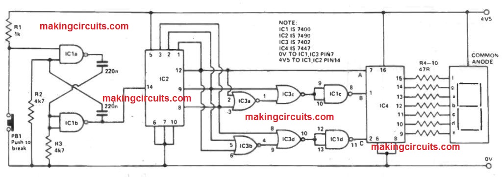
Such that the display is equivalent to a dice the display should read 1-6 rather than 0-5, once the output from the 7490 is all "O's, the display need to be designed to display 6.
IC1c, d and IC3 execute this activity, and transform an output of 000 via IC2 to 110 (b). IC4 is a BCD to 7 -segment decoder that illuminates the display with the current limit resistors R4 -R 10.
Touch Pad Random Die Circuit
A typical operation of a die is demonstrated in this easy looking circuit. Equipped with a Schmitt-trigger gate oscillator, clock pulses are generated relentlessly as soon as the touch pad is touched with finger.
No matter for many seconds you touch the touch pads, the output will inevitably generate an unbiased random figure, by illuminating different sets of or numbers of LEDs.
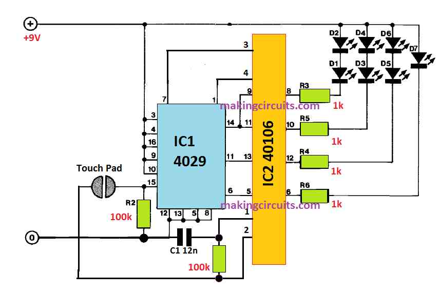
You can observe them at the relevant input of a Type IC 4029 binary counter which is preloaded to state 9 through the inputs J0 to J3.
In contrast, the outputs Q0 to Q2 may signify one of six arbitrary states of 9 to 15 when you lift your finger from the touch-sensitive contacts between the oscillator and counter-clockwise input.
On preset 1, counter output states of 9 to 15 were chosen instead of 1 to 6 because the Carry Out (CO) could be attached to Preset Enabled (PE) through inverter N2.
This configuration results in the binary values at Q0 to Q2 outputs to differ between 1 and 6 as Q3 is undisturbed.
Then, CO goes low when the counter counts to output state 16, which cannot be translated to any four-digit binary code (outputs) to the IC.
Therefore, a preset value of 1 (9) is loaded by the counter as PE goes high. Correspondingly, LEDs D1 to D7 are aligned in a standard form.
is there an older design of the electronic dice design
touch pad dice looks similar to electronic dice, a technology project for secondary education for the eu school net. only difference is there is no diode in the circuit and the resistors have somewhat different values.