• Skip to main content
  • Skip to primary sidebar

Making Easy Circuits

Learn and build electronic circuits

You are here: Home / Protection Circuits / Electronic Fuse Circuit for Power Supply  

Electronic Fuse Circuit for Power Supply  

Last Updated on January 10, 2018 by Admin Leave a Comment


Electronic circuit current fuse has gained popularity in recent times, especially when it comes to structured power resource and power assembled circuits. The classic fuse tube, which was quite popular once gets fused when placed on wrong PCB during testing, barring some hi-priced one. It is for this reason that many semi-conductors have lost their use and sunk in oblivion.


Keeping the aforesaid issue in consideration it is thus better to use those electronic fuse that are fast enough [100 times faster] and moreover where current flow can be managed flowing in to the load. While it is evident of the tremendous benefits using such fuse, a question obviously comes in mind as why it is not being used extensively in the power sources? The main reason for such factor is primarily for the cooling power element [BUZ11 Transistor]. When in normal state with the lock not in active mode the loosing of heat is minimal. This is for the switching transistor having low resistance. However, the scenario is getting different these days. With the activation event of the recent fuse, the power transistor gets assigned serially to a resistor to the path of the current flow. It is for this reason that losses what occurs during this state, becomes directly proportional to the voltage supply, thus setting up the constraint.
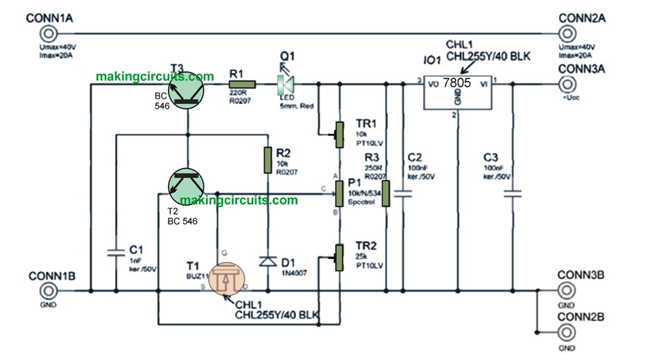


electronic fuse circuit for power supply

How it works?


The maximum current output of the fuse can be set to 10 mA (approx.). The maximum current that can be allowed is what the transistor can take (BUZ11 – 20A). The fuse used in the circuit has +5V of power supply along with a 7805 integrated stabilizer and reference voltage of +5V. Keeping this in mind, it is imperative that stability is one of the prime factors to an accurate measurement of current limit.  The system is controlled by the potentiometer [here Spectrol 534 of 10 units are used. Alternatively, you can also use two potentiometers of which one can be used for adjust coarseness and the other to achieve clarity. In order to manage the constraints in current fuse, you can use a LED Diode Q1 [green].

You'll also like:

  • 1.  Make this 12V 1A SMPS Circuit
  • 2.  +/- 15V Dual Regulated Power Supply Circuit
  • 3.  How to Protect Homes from Burglars during Vacations
  • 4.  Understanding the IC 7805, 7812, and 7824 Pinout Connections
  • 5.  Making an Adjustable Voltage, Current Power Supply Circuit Using Transistor 2N3055
  • 6.  1A Voltage Regulator better than 7805, 7812

About Admin

Hey friends, Thanks a bunch for stopping by this site! I am an engineer with a Bachelor of Engineering in Electronics and Telecommunication. One of my passions is gathering information from all sorts of electronics books and tutorials. I then take that information and compile it into a language that is super easy to understand. My goal is to make those complex electronics circuit concepts and technical terms much more accessible for all the new and budding electronics engineers out there. I can also design customized circuit diagrams as required by the users.
If you have any questions related to this field, please do not hesitate to drop a comment! I am always here and ready to help you out with any queries you might have. I cannot wait to hear from you!

Reader Interactions

Leave a Reply Cancel reply

Your email address will not be published. Required fields are marked *

Primary Sidebar

Categories

  • 3 Phase (4)
  • 8051 Microcontroller (1)
  • Arduino (11)
  • Audio and Amplifier (102)
  • Automation (8)
  • Battery Chargers (64)
  • Bicycle Projects (4)
  • Car and Motorcycle Projects (39)
  • Datasheets (10)
  • DIY Projects (5)
  • Electrical (15)
  • Free Energy (6)
  • Games Projects (2)
  • High Voltage (14)
  • Hobby Projects (30)
  • Household Circuits (2)
  • IC 555 Circuits (5)
  • Ignition Circuits (2)
  • Indicators (50)
  • Infrared (6)
  • Inverter Circuits (29)
  • Lights and Lamps (97)
  • Medical (8)
  • Meter and Tester Circuits (38)
  • Motor Driver (17)
  • New Circuits (56)
  • Oscillators (30)
  • Pets and Pests (5)
  • Power supply (80)
  • Protection Circuits (25)
  • PWM (9)
  • Remote Control (20)
  • Security and Alarm Circuit (48)
  • Sensors and Detectors (66)
  • Signal Processor (23)
  • Solar Controller Circuits (62)
  • SSR (3)
  • Temperature Controller (20)
  • Timer (25)
  • Transformerless (7)
  • Transmitters (12)
  • Tutorials (45)
  • UPS (2)
  • Voltage Regulators (57)
  • Water Sensor and Controller (29)
  • Home
  • Privacy Policy
  • Contact
  • Disclaimer
  • Copyright

© 2025 · Making Easy Circuits