• Skip to main content
  • Skip to primary sidebar

Making Easy Circuits

Learn and build electronic circuits

You are here: Home / New Circuits / Electronic Toss Circuit

Electronic Toss Circuit

Last Updated on October 30, 2020 by Admin Leave a Comment

We have seen a coin is tossed before beginning a football match. This electronic version of it comes with a row of 7 LEDs – the middle one is green, and the rest are red.

When you press reset, the probability of the red LEDs next to the green LED to light are the same for all the red LEDs. Thence, a left or right decision is conducted by the circuit based on complete randomness.

How the Circuit Works

The operation is simple. Button S1 can be activated at any time to preset the counter IC1.

led dice circuit compressed

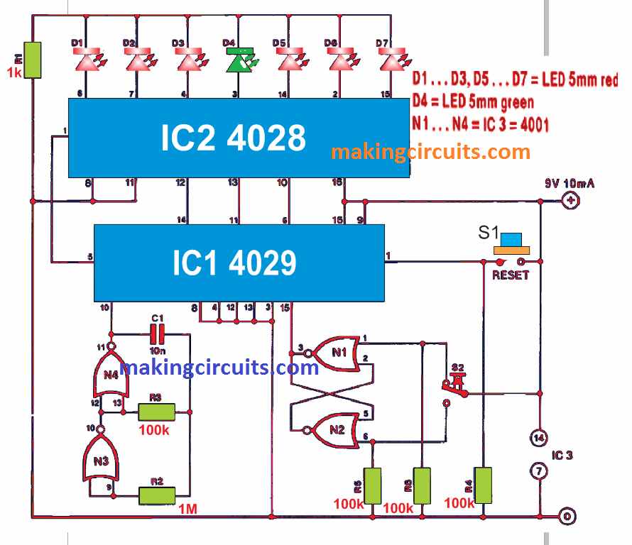
This component returns a binary value of 0 at Q0, Q1 and Q2 outputs. As a result, the BCD-to-decimal decoder, IC2, converts the bits to the corresponding green LED (D4) in the middle of the row.

You can preset the initial state of the circuit by activating P6 to P3 while they are connected to the ground. This signals IC1 to load 0000 as the initiating binary digits when button S1 is pushed.

When you press the button S2, switching of N1 and N2 happens. As a result, a single pulse transition develops at the clock input of IC1. Based on the logic at the UP/DOWN input of IC1, the 1/8 decoder will light up D5 (on the right) or D3 (on the left).

This tallies with the counting up sequence from 0000 to the next binary number, 0001. On the other hand, if counting is downwards, a value of 1111 is delivered. When the value is counted down, IC2 will let D3 light up at the output of Q7. This happens because the most significant input bit of D is connected to the ground.

Toss Results are 100% Random

The randomness of the toss-up circuit is guaranteed by the speed of the pulse applied to the counter UP/DOWN input by oscillator N3-N4. In theory, the odds are personalised and cannot be tampered with.

7 active-high outputs of IC2 are attached to their related LEDs. At the same time, Q4 aids to impede the counter through the CARRY IN terminal. You may notice the counter limitation happens automatically as IC1 counts up from the state 3 output. If state 5 is concerned, the IC counts down. Both these situations allow Q4 and the CARRY IN to go HIGH. As a result, the counting will not continue as long as the reset button is not pressed.

In the end, if you continuously press the S2 button without resetting the circuit, any random LED will illuminate. This is useful when you are playing any other random-based game.

You'll also like:

  • 1.  Water Temperature Controller Circuit for Central Heating Systems
  • 2.  How to Make a Pyrometer Circuit
  • 3.  How to Change Fluorescent Tubes to LEDs
  • 4.  Easy FET Circuits you can Build and Use
  • 5.  Single Phase Preventor Circuit
  • 6.  Discotheque Music Level Indicator Circuit

About Admin

Hey friends, Thanks a bunch for stopping by this site! I am an engineer with a Bachelor of Engineering in Electronics and Telecommunication. One of my passions is gathering information from all sorts of electronics books and tutorials. I then take that information and compile it into a language that is super easy to understand. My goal is to make those complex electronics circuit concepts and technical terms much more accessible for all the new and budding electronics engineers out there. I can also design customized circuit diagrams as required by the users.
If you have any questions related to this field, please do not hesitate to drop a comment! I am always here and ready to help you out with any queries you might have. I cannot wait to hear from you!

Reader Interactions

Leave a Reply Cancel reply

Your email address will not be published. Required fields are marked *

Primary Sidebar

Categories

  • 3 Phase (4)
  • 8051 Microcontroller (1)
  • Arduino (11)
  • Audio and Amplifier (102)
  • Automation (8)
  • Battery Chargers (64)
  • Bicycle Projects (4)
  • Car and Motorcycle Projects (39)
  • Datasheets (10)
  • DIY Projects (5)
  • Electrical (15)
  • Free Energy (6)
  • Games Projects (2)
  • High Voltage (14)
  • Hobby Projects (30)
  • Household Circuits (2)
  • IC 555 Circuits (4)
  • Ignition Circuits (2)
  • Indicators (50)
  • Infrared (6)
  • Inverter Circuits (29)
  • Lights and Lamps (97)
  • Medical (8)
  • Meter and Tester Circuits (38)
  • Motor Driver (17)
  • New Circuits (56)
  • Oscillators (30)
  • Pets and Pests (5)
  • Power supply (81)
  • Protection Circuits (25)
  • PWM (8)
  • Remote Control (20)
  • Security and Alarm Circuit (48)
  • Sensors and Detectors (66)
  • Signal Processor (23)
  • Solar Controller Circuits (61)
  • SSR (3)
  • Temperature Controller (20)
  • Timer (25)
  • Transformerless (7)
  • Transmitters (12)
  • Tutorials (45)
  • UPS (2)
  • Voltage Regulators (57)
  • Water Sensor and Controller (29)
  • Home
  • Privacy Policy
  • Contact
  • Disclaimer
  • Copyright

© 2025 · Making Easy Circuits