Here we are discussing soldering irons but not just any soldering irons. We are talking about a super smart energy saving soldering iron station that is designed to be a total champ when it comes to conserving power. The whole idea here is to make sure that your soldering iron is not just sitting there wasting electricity and potentially overheating when you are not actually using it. It is a real concern and we are here to tackle it!
So what we are going to do is figure out how to build a circuit that automatically switches the soldering iron OFF when it realizes you have taken a break or gotten distracted by that cat video you saw online.
DESIGN #1:
Okay so the main goal here is to create a circuit for your soldering iron that does not just save energy but also stops the soldering iron tip from getting too hot and bothered. We are aiming for maximum efficiency so that is why we are here.
ANALYSIS & THE GAME PLAN
Alright so here is how this whole thing is supposed to work step by step:
a) First you flip the switch and turn ON the soldering iron. Give it about a minute to warm up and get ready for action. We want it to be at peak performance.
b) Next the circuit needs to figure out whether the soldering iron is resting in its stand or not.
c) Now here is the clever part. If the soldering iron is not in its stand meaning you are actively using it then it gets the full treatment: 100% power straight from the AC mains. It is full power all the time.
d) But if the soldering iron is relaxing in its stand then it only gets a little sip of power about 20% through a regulated circuit. This is just enough to keep it warm and ready to go without wasting a ton of energy or overheating the tip. It is a low power mode for when it is not in use.
e) And then the whole process starts over again from step (b). The circuit keeps checking to see if the soldering iron is constantly adjusting the power level to save energy and prevent overheating. It is a continuous cycle of monitoring and adjusting.
And that is basically the gist of it! Keep in mind this is just a broad overview. There is a lot more that goes into building the actual circuit but hopefully this gives you a good idea of what we are trying to accomplish. Now let us learn the setting up of the circuit.
CIRCUIT DESCRIBED:
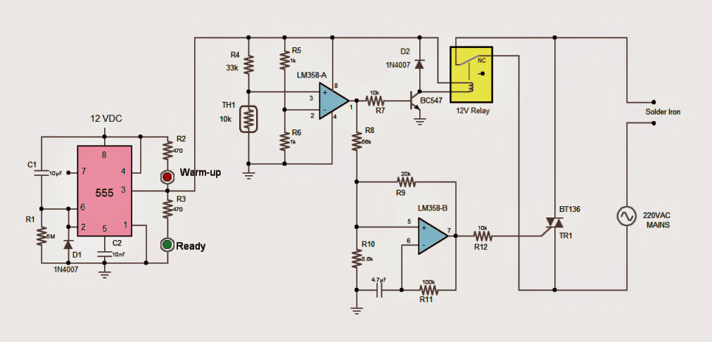
a) First up there is a 555 timer. This delays the power from turning on for about a minute. The soldering iron is hooked up to the AC power line through "NC" relay contacts during this grace period. "NC" means "Normally Closed". There is a red LED that shines during the warm up minute. When it is over the red light goes off and a green LED turns on signaling that the irons ready.
b) Next an IC called LM358 A acts as a voltage checker to see if the soldering iron is in its stand. It uses a thermistor for this which is a resistor that changes resistance with temperature.
The comparators (-)ve input gets a steady 6V using resistors R5 and R6 as a potential divider. The (+)ve input also connects to a potential divider with R6 and the thermistor TH1.
If the irons not in its stand the thermistor remains at room temperature. At room temperature the thermistors resistance is around 10k. The R4/TH1 potential divider then gives about 2.8V at the (+)ve input less than the 6V at the (-)ve input. The LM358 As output stays low and nothing changes. The iron keeps getting power through the relays "NC" contacts.
c) Now if the iron is in its stand the temperature rises increasing the thermistors resistance. When it goes above 33k the R4/TH1 potential divider provides more than 6V at the (+)ve input. The LM358 As output then goes HIGH.
This HIGH output fires up the relays coil via transistor T1. The relay then disconnects the soldering iron from the AC power. So the irons off when it is in its stand.
But The HIGH output from LM358 A also powers LM358 B set up as an astable oscillator. This creates a repeating on off signal. This oscillator has a duty cycle of about 20% meaning it is on 20% of the time and off 80%.
The potential divider R8/R10 controls the duty cycle. The oscillators output goes to the gate of a triac BT136. The triac acts like a switch rapidly turning on and off. When the triacs on power flows to the iron for 20% of the cycle. This gives the iron only 20% of its normal power saving energy while it rests.
IMPORTANT THINGS TO KEEP IN MIND:
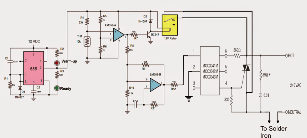
The triac is directly connected to the rest of the circuit through resistor R12 so be super careful and do not touch it when powered on. An opto isolator like the MOC3020 can add extra protection.
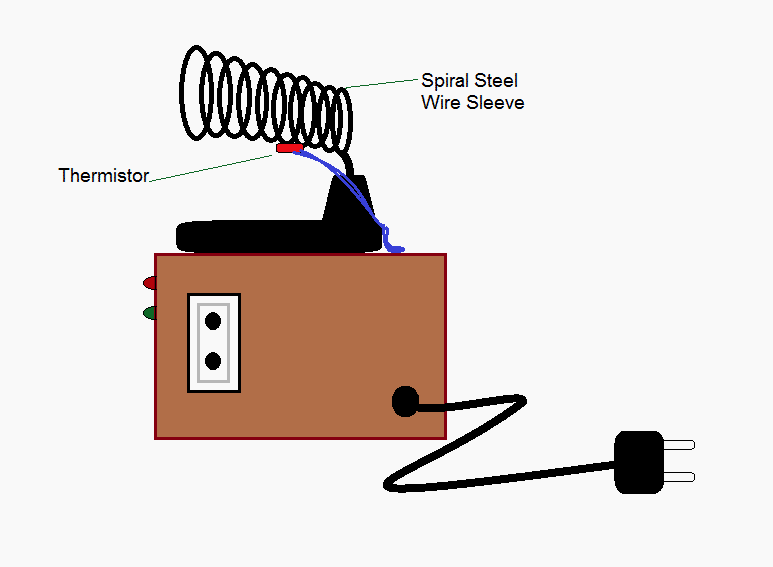
Any thermistor value works but choose R4 accordingly to provide about 3V at normal temperature. Also consider that the spiral steel wire sleeve around the thermistor will heat up affecting the thermistors resistance.
You cannot replace the triac with a relay because of the annoying clicking and potential high voltage sparks.
Cover the thermistor legs with heat resistant insulation and mount it securely on the iron stand.
Yet another straightforward automated soldering iron power shut-off timer circuit is covered in the following idea below. This circuit makes certain that the iron always has the power off, regardless of whether the user overlooks to do so while doing this common electronic assembly task. Mr. Sam asked the concept.
Technical Details for Design #2
I'm Sam from the UK, and I work as a repair technician. However, I have a challenge: I usually lose sight of to turn on the soldering iron. To help me, I've thought of a circuit that can disconnect itself on its own.
The low-power soldering iron eventually split in half.
and beeps unless you hit a switch to reset the countdown to zero; if you don't press it, it turns off.
I already want to thank you.
Description of the Circuit
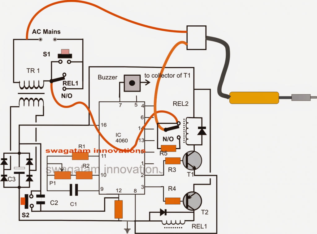
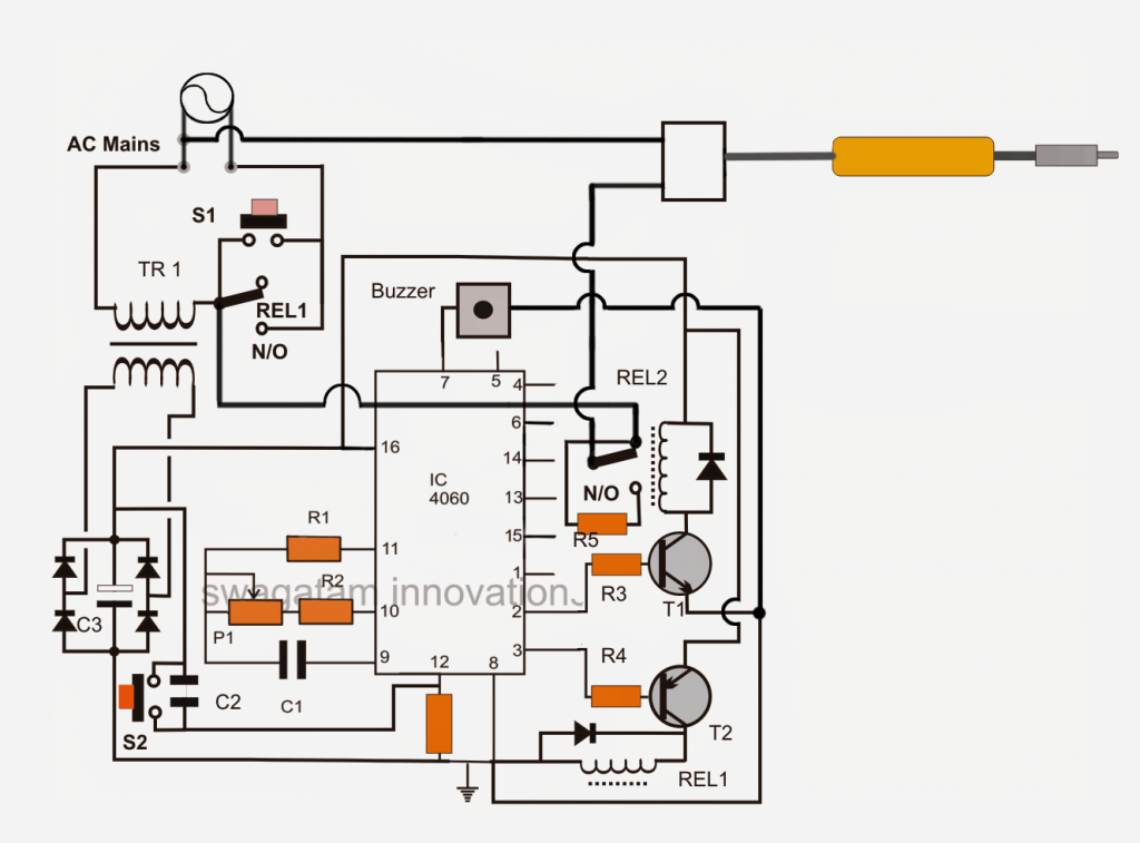
Because the REL1 contacts are disabled, the circuit in the beginning remains turned OFF whenever energized by mains AC.The IC 4060 is briefly energized by TR1, bridge network enabling T2, right away as S1 is pushed.
T2 immediately energizes the REL1 coil at its collector, triggering the REL1 connected across S1's N/O contacts.
Bypassing S1 and latching the circuit, the aforementioned activation maintains REL1 engaged even after S1 is released.
Additionally, this turns on the soldering iron that is linked by REL1 and REL2's N/C.
IC 4060, that is connected as a timer and energized, now starts counting the duration of the period that has been established by modifying P1 in accordance with the specifications.
Assume that pin 3 of the IC is configured to get high after ten minutes if P1 is set for ten minutes.
But it also implies that after five minutes, pin 2 of the IC would become high.
After five minutes of pin 2 turning on, REL2 is triggered, changing its contacts from N/C to N/O. Here, N/O is linked to the iron with a high-watt resistor, which switches the iron to receive less current and lowers its temperature below the range that is optimal.
When T1 is turned on in the aforementioned scenario, the buzzer at pin 7 receives the necessary ground supply from T1 and begins to sound at a certain frequency, signifying that the iron has been moved to the low heat position.
The person using it can currently press S2 to reset the IC timing return to zero if they would like to return the iron to its initial state.
On the other hand, if the individual using it is not paying attention, the situation continues for a further five minutes, for a total of ten minutes, whereupon pin 3 of the IC likewise gets high, turning off T1 and REL1, causing the circuit to automatically shut down.
Circuit Diagram
Parts List
| Component | Value/Specification |
|---|---|
| R1 | 100K |
| R2, R3, R4 | 10K |
| P1 | 1M |
| C1 | 1uF NON POLAR |
| C2 | 0.1uF |
| C3 | 1000uF/25V |
| R5 | 20 OHMS 10 WATT |
| ALL DIODES | 1N4007 |
| IC PIN12 RESISTOR | 1M |
| T1 | BC547 |
| T2 | BC557 |
| REL1, REL2 | RELAY 12V/400 OHMS |
| TR1 | 12V/500MA TRANSFORMER |
| S1/S2 | PUSH TO ON SWITCHES |
| BUZZER | ANY 12V PIEZO BUZZER UNIT |
A revised version of the preceding schematic is shown below; the gentleman in question made the necessary improvements to make the wiring complexities simpler to grasp.
Extremely low-cost but efficient soldering Iron Energy-Saving Protection System
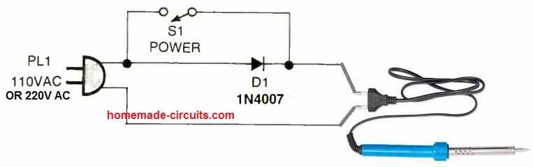
Possibly the least expensive soldering iron protection and energy-saving circuit is this one. As is well known, when a single rectifier diode receives power from the AC mains, it permits 50% of the AC mains' phases to flow via it while blocking the other half cycle.
This indicates that the diode can only handle 50% of the power. In order to manage the power using the soldering iron, we utilize the diode's half wave rectification theory in this circuit.
The switch S1 is deactivated to allow only 50% electricity to be supplied to the iron via the diode while the iron is in state of idleness and not in use, as shown in the illustration above.
This keeps the iron's heating at a respectable level while using just 50% of the electricity.
Switch S1 remains on when the iron is being used, bypassing the diode and allowing the entire AC supply to swiftly approach the soldering iron and return it to its optimum heat.
Leave a Reply