Three phase electricity, we can say that it is basically one method which we use to make electric power and send it over very long distance so that offices, factories, and industries can use it properly.
In this system we are dealing with three phase voltages and three phase currents and we can increase them or decrease them as required, since we are using three phase transformers for this job.
These transformers are quite flexible because their windings can be connected in different different ways, that depends on what kind of voltage and current we actually need at the output.
Till now we were mostly talking about the simple single phase two winding voltage transformer because that one is easy to understand and easy to use.
This type of transformer helps us to change the secondary voltage in relation to the primary supply voltage so now it becomes very useful for basic applications.
But now things become a little more interesting because we can also design voltage transformers which do not connect to only one phase, but to two phases, three phases, six phases and even very complex arrangements that can go up to twenty four phases, especially when we talk about DC rectification transformers.
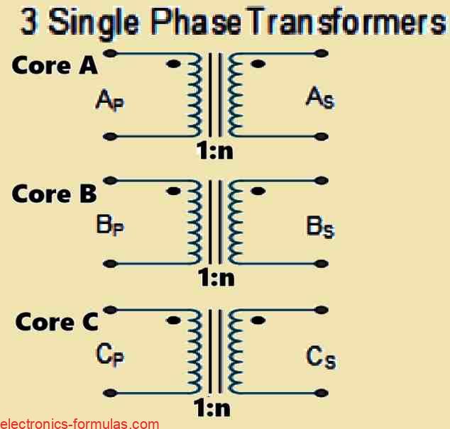
Now let us imagine that we take three separate single phase transformers and we connect their primary windings together, and also connect their secondary windings together in a specific pattern, then we can actually operate these transformers using a three phase power supply.
So now instead of using one big three phase transformer, we are using three single phase units working together.
When we talk about three phase power which you may see written as 3 phase or sometimes as 3φ, we are actually talking about a system which is used for generating electrical power, transmitting it over distance, and then distributing it to users.
This system is also very commonly used in industrial applications, since machines and heavy loads work better with three phase supply.
One important thing about three phase supply is that it gives many electrical advantages compared to single phase power.
When we think about three phase transformers, we must remember that we are handling three alternating voltages and three alternating currents and these are not moving together, but they are shifted from each other by 120 degrees in phase time. So now this phase difference is what makes the whole three phase system work smoothly.
Understanding Three Phase Voltages and Currents
It is not possible for a transformer to work as a one phase to three phase changer or three phase to single phase changer because a transformer does not change phase by itself but only transfers power. When we want a transformer to work with a three phase supply then we must connect the windings together in a proper way, so now a three phase transformer arrangement can be created and used correctly.
We can make a three phase transformer in two main ways so now one way is by joining three single phase transformers together and this is called a three phase transformer bank. Another way is by using a single ready made balanced three phase transformer which is built using three pairs of single phase windings that are fixed on one laminated core, so everything stays together.
Since copper and iron core material is used in a more effective manner in a single three phase transformer, so now this type of transformer becomes smaller in size lighter in weight and also cheaper to manufacture when compared to using three separate single phase transformers for the same kVA rating.
Whether we use one single three phase transformer or we use three independent single phase transformers, the method of connecting the primary winding and the secondary winding remains exactly the same, so now let us look at and understand the configuration that is shown below.
Analyzing Three Phase Transformer Configurations
It is not possible for a transformer to work as a one phase to three phase changer or three phase to single phase changer because a transformer does not change phase by itself but only transfers power.
When we want a transformer to work with a three phase supply then we must connect the windings together in a proper way, so now a three phase transformer arrangement can be created and used correctly.
We can make a three phase transformer in two main ways, so now one way is by joining three single phase transformers together and this is called a three phase transformer bank.
Another way is by using a single ready made balanced three phase transformer which is built using three pairs of single phase windings that are fixed on one laminated core, so everything stays together.
Since copper and iron core material is used in a more effective manner in a single three phase transformer, so this type of transformer becomes smaller in size lighter in weight and also cheaper to manufacture when compared to using three separate single phase transformers for the same kVA rating.
Whether we use one single three phase transformer or we use three independent single phase transformers the method of connecting the primary winding and the secondary winding remains exactly the same, so now let us look at and understand the configuration that is shown below.
Understanding Three Phase Transformer Connections
A transformer primary and secondary windings can be linked in many different ways and we can see that this is done to meet almost any practical need.
We see three main types of connections used with three phase transformer windings and these are called interconnected-star zigzag delta mesh and star wye.
We use these connections because different electrical systems need different voltage and current behavior, so now engineers choose the connection carefully.
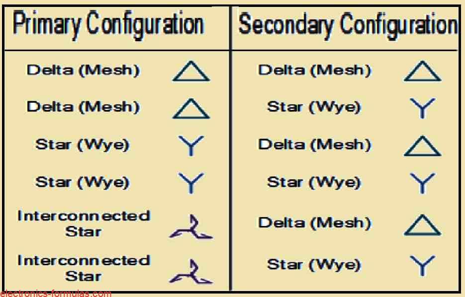
Depending on how the transformer is planned to be used we can see that the winding arrangement may be primary delta with secondary star or star-delta or star-star or delta-delta.
Since the application decides everything so now the same transformer idea is used in many forms. In general we call a transformer a polyphase transformer when it is configured to deliver three or more phases and this name is used commonly in electrical systems.
Understanding Star And Delta Transformer Behavior
When we choose the type of electrical connection on the primary side and the secondary side we must also think about the three possible voltages.
These voltages are separated by 120 electrical degrees and this separation controls how the transformer current flows. So now voltage relationship and current behavior are both linked together in this system.
When three single-phase transformers are connected together, there is a 120 time-degree phase difference between the magnetic flux in each transformer.
We can say that three magnetic flux values exist with 120 degree time-phase difference inside the core of a three-phase transformer and this happens naturally because of the three phase supply.
The three primary windings of a three-phase transformer are usually marked using capital letters A B and C.
These letters represent the three phases RED YELLOW and BLUE, so now identification becomes easy during installation and testing.
The secondary windings are marked using small letters a b and c and this helps us understand which side is primary and which side is secondary.
For example the second winding of the primary will have ends named B1 and B2. In the same way the third winding of the secondary will have ends named c1 and c2 as shown in diagrams.
This is done because every winding has two ends and these ends are normally marked as 1 and 2 so now tracing connections becomes simple.
Understanding Star And Delta Transformer Configurations
On a three-phase transformer we often see small icons used to show what type of interconnection is present.
We can see that these icons are helping us understand how the windings are connected so we do not get confused.
We look at lower case y d and z which are used for the secondary windings.
We also see upper case Y which means Star connected D which means Delta connected and Z which means linked Star primary windings so now we can identify things easily.
When transformers are wired in the same way then we explain the connection by using simple letter pairs so that you and we can read it fast.
Interconnected Star to interconnected Star is written as Zz. Delta to Delta is written as Dd.
Star to Star is written as Yy. We write it like this so anyone can understand how the transformer connections are done.
Using a Table to Understand 3 Phase Transformer Winding
| Connection | Primary Winding | Secondary Winding |
| Delta | D | d |
| Star | Y | y |
| Interconnected | Z | z |
So now we can see that we have four possible configurations for connecting three single-phase transformers between their primary and secondary three-phase circuits as we already know.
We understand that these configurations are Delta-Delta (Dd) and Star-Star (Yy) and Star-Delta (Yd) and Delta-Star (Dy). So these are the common combinations that we normally see and use in three-phase transformer systems.
When we compare delta transformers with star connections we can say that high voltage transformers using star connections have a clear advantage.
That advantage is that the voltage on a single transformer becomes lower since fewer number of turns are required and larger conductors can be used, so now insulation for the coil windings becomes simpler and also less expensive for us to design and build.
But now the delta-delta combination has one strong advantage when we compare it with the star-delta arrangement.
If one of the three transformers in the group becomes faulty or stops working then the other two transformers will continue operating, so they will still supply three-phase power with a capacity that is close to two thirds of the transformer initial output.
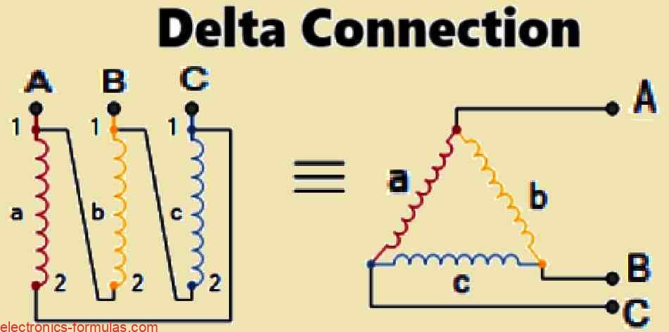
Understanding the Delta-Delta 3-Phase Transformer Configuration
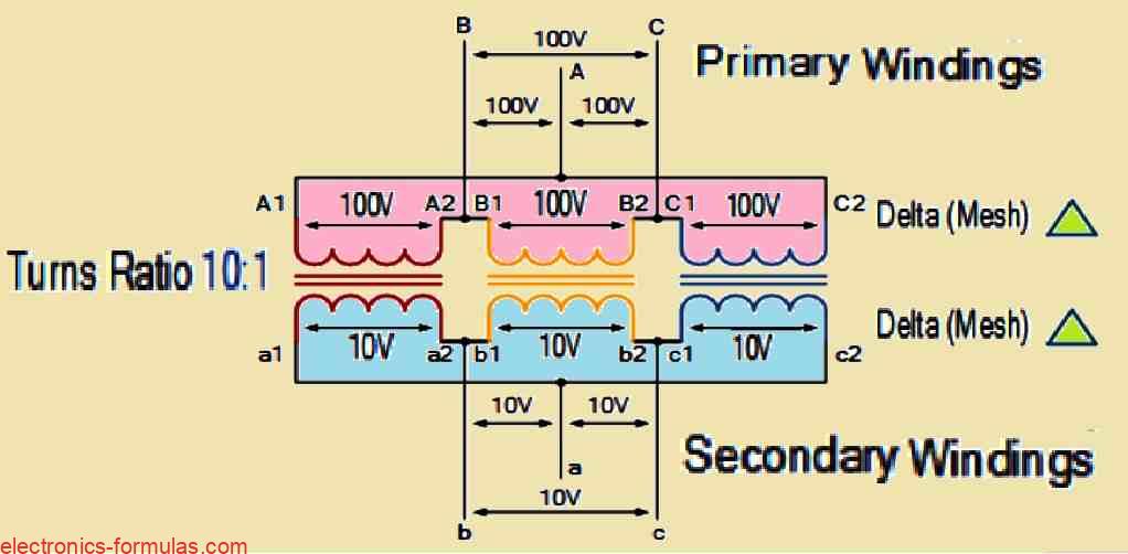
The line voltage (VL) in a delta linked (Dd) set of transformers is exactly the same as the supply voltage (VL = VS).
We can say that this is simple to understand because the supply directly matches the line side, but for each phase winding the current is not same like line current.
We see that the current is expressed as 1/√3 × IL of the line current, here IL is the line current and that is how the phase winding current behaves in this connection.
Now we see that every single transformer must have a winding for the full line voltage which in our case is over 100V.
At the same time it must also handle only 57.7% line current.
This situation looks like a drawback for delta connected three phase transformers.
We feel this because the design becomes heavier and more demanding.
When we compare this with the star connection then a bigger and more costly coil is required in delta connection.
This happens because the winding has higher number of turns and also needs stronger insulation between turns.
Another drawback we can see is that there is no neutral or common connection in delta connected three phase transformers, so this creates limitation in some applications.
In the star star (Yy) or wye wye configuration every single transformer has one terminal attached to a neutral point or common junction.
The three remaining terminals of the primary windings are linked to the three phase mains supply.
In any star connection the transformer winding needs only 57.7% of the turns required for a delta connection so we can see this is one clear advantage.
A total of three transformers are needed for the star connection.
If one of them fails then all the others can also get deactivated, but in electrical power distribution systems the star connected three phase transformer is very efficient and also cost effective.
This is because a fourth wire can be attached which works like a neutral point (n) for the three star connected secondaries.
Understanding The Star Star 3 Phase Transformer Configuration
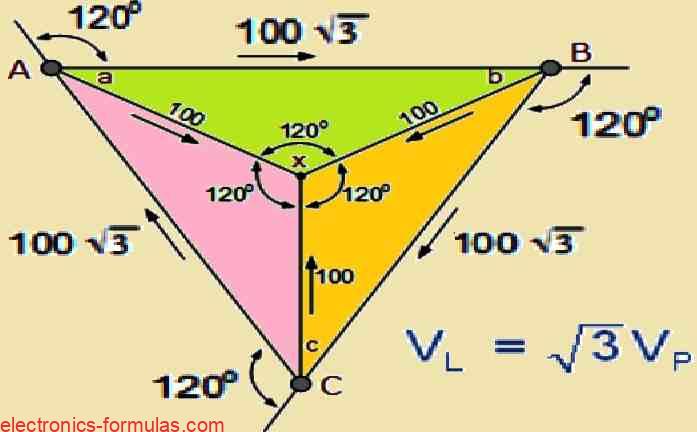
The line voltage or VL is the voltage between any two lines in a three phase transformer. The phase voltage or VP is the voltage between any line and the neutral point in a star connected transformer.
This phase voltage is equal to 1/√3 × VL of the line voltage so now the primary side phase voltage VP can be calculated like this.
VP = (1/√3) * VL = (1/√3) * 100 = 57.7 Volts
If the line current of the electricity source and the secondary current in each phase of a star connected set of transformers are equal then IL = IS.
In a three-phase electrical supply, the connection between line and phase voltages and currents could therefore be concluded up as follows:
Table to Sum up the Three-phase Voltage and Current
| Connection | Phase Voltage | Line Voltage | Phase Current | Line Current |
| Star | VP = VL ÷ √3 | VL = √3 * VP | IP = IL | IL = IP |
| Delta | VP = VL | VL = VP | IP = IL ÷ √3 | IL = √3 * IP |
Again this time we can see from the main side or even from the secondary side that VP is showing the phase to neutral voltage while VL is showing the line to line voltage, so this is how we understand these two terms in simple way.
Three phase transformers can also be wired in different ways and we can see delta star Dy where the primary is delta connected and the secondary is star connected, or we can see star delta Yd, where the primary winding is star connected and the secondary winding is delta connected.
When the main windings are supplying the utility company with a three wire balanced load and the secondary windings are supplying the required fourth wire neutral or ground connection, then delta star connected transformers are used many times in low power distribution systems.
The total turns ratio of the transformer becomes more confusing when the primary and secondary have independent winding connections like star or delta, because both sides are not connected in same way.
There is a possibility that a three phase transformer with a 1:1 turns ratio is connected as delta delta Dd or star star Yy. This clearly means that the input voltage and output voltage of the windings are equal.
For low power distribution delta star connected transformers are again used very commonly. The electricity distribution company receives a three wire balanced load from the primary windings while the secondary windings give the required fourth wire neutral or earth connection.
Because the primary and secondary have separate winding connections like star or delta this again makes the total turns ratio calculation more complex.
A three phase transformer can have a 1:1 turns ratio when it is connected as delta delta Dd or star star Yy. This simply means the input and output voltages of the windings stay equal.
On the other hand every star connected main winding will receive the supply phase voltage VP which is nearly equal to 1√3 × VL when the three phase transformer is connected in star delta Yd.
Since these windings are delta connected the voltage 1√3 × VL will later become the secondary line voltage because the same voltage is induced in each matching secondary winding.
So now a star delta connected transformer will finally produce a √3:1 step down line voltage ratio when the turns ratio is 1:1.
Because of this the turns ratio calculation for a transformer with star delta Yd connection becomes as follows.
Formula for Star-Delta Turns Ratio
TR = NP/NS = VP/(√3 * VS)
Similarly a transformer connected to a delta-star (Dy) with a 1:1 turns ratio will increase the line-voltage ratio by a factor of 1:√3. As a result, the turns ratio for a transformer with a delta-star connection will be:
Formula for Delta-Star Turns Ratio
TR = NP/NS = (√3 * VP)/VS
Table Indicating Three-phase Transformer Line Voltage and Current
We could subsequently describe the secondary voltages and currents of the transformer for each of the four fundamental three-phase transformer topologies with regards to the primary line voltage VL and its primary line current IL, as shown in the table below.
| Primary-Secondary Configuration | Line Voltage, Primary or Secondary | Line Current, Primary or Secondary |
|---|---|---|
| Delta-Delta | VL → n * VL | IL → IL / n |
| Delta-Star | VL → √(3) * n * VL | IL → IL / (√(3) * n) |
| Star-Delta | VL → (n * VL) / √(3) | IL → (√(3) * IL) / n |
| Star-Star | VL → n * VL | IL → IL / n |
In the above table, VL represents the line-to-line voltage and VP indicates the phase-to-neutral voltage, and n denotes the transformer's "turns ratio" (T.R.) of the number of secondary windings (NS) divided by the amount of primary windings: (NP) * (NS/NP).
Solving a 3-Phase Transformer Problem #1
A 110 volt 60Hz three-phase supply powers the primary winding of a delta-star (Dy) connected 60VA transformer. Calculate the secondary side voltages and currents assuming the transformer's primary winding contains 600 turns and its secondary winding comprises 120 turns.
Given:
- Primary voltage (VL(primary)) = 110 V
- Frequency = 60 Hz
- Transformer power = 60 VA
- Primary turns (Np) = 600
- Secondary turns (Ns) = 120
- Configuration = Delta-Star (Dy)
- Determine the turns ratio:
- n = Ns / Np
- n = 120 / 600
- n = 0.2
- Calculate the secondary line-to-line (line) voltage:
For a delta-star configuration, the secondary line voltage is:
VL(secondary) = √(3) * n * VL(primary)
Let's Substitute the values:
VL(secondary) = √(3) * 0.2 * 110 VL(secondary) ≈ 38.1 V
- Calculate the secondary phase voltage:
In a star connection, the phase voltage is related to the line voltage by:
Vph(secondary) = VL(secondary) / √(3)
Let's Substitute the values:
Vph(secondary) = 38.1 / √(3) Vph(secondary) ≈ 22.0 V
- Calculate the secondary phase current:
The phase current is derived from the transformer power and phase voltage:
Iph(secondary) = Power / (3 * Vph(secondary))
Substitute the values:
Iph(secondary) = 60 / (3 * 22.0)
Iph(secondary) ≈ 0.91 A
- Calculate the secondary line current:
In a star connection, the line current will be equal to the phase current:
IL(secondary) = Iph(secondary)
So, IL(secondary) ≈ 0.91 A
Final Answers:
- Secondary Line Voltage (VL(secondary)) ≈ 38.1 V
- Secondary Phase Voltage (Vph(secondary)) ≈ 22.0 V
- Secondary Line Current (IL(secondary)) ≈ 0.91 A
- Secondary Phase Current (Iph(secondary)) ≈ 0.91 A
Understanding Three Phase Transformer Construction
As we already talked before a three-phase transformer is actually working like three single-phase transformers which are connected together and they sit on one common laminated core.
When we take these three windings and put them together on one single magnetic circuit like we see in the diagram then we can save a lot of cost and also space and also weight which becomes very useful in real design.
The three magnetic circuits which are normally linked inside a three-phase transformer help to spread the dielectric flux properly between the high voltage winding and the low voltage winding so that operation becomes balanced and smooth.
But now we must understand that a transformer which uses a three-phase casing can behave a little different, because even though the windings are connected the three cores in the shell form structure are not magnetically interconnected, so they work in a separate manner even while staying inside the same body.
Internal Construction of a Standard Three Phase Transformer
Three-phase transformers are used in many places and we can see that one common design way is there.
This design helps magnetic coupling of the phases and people mostly use three-limb core-type construction. This method is simple and it works well so many engineers follow it.
Inside the core there are three magnetic fluxes and these come from the line voltages which change with time-phase by 120 degrees.
Each limb flux does not travel alone and it uses the other two limbs to return back, because of this action the flux inside the core makes a sinusoidal secondary supply voltage and this voltage stays almost like a sinusoidal waveform so the output looks clean and smooth.
When we compare core-type with shell-type core then the five-limb type three-phase transformer architecture becomes heavier and also it costs more to make.
This is because more iron and more structure is needed so weight and cost both increase.
Since five-limb cores can be made with less height then these are mostly used for very big power transformers.
The core components electromagnetic windings metal housing and conditioning of a shell-type transformer are almost same like the big single-phase models and people already know how to handle these parts so the design stays familiar.
References:
Leave a Reply