• Skip to main content
  • Skip to primary sidebar

Making Easy Circuits

Learn and build electronic circuits

You are here: Home / Meter and Tester Circuits / Field Strength Meter Circuit using a BJT

Field Strength Meter Circuit using a BJT

Last Updated on April 6, 2020 by Admin Leave a Comment

Simple field strength indicator circuit enables us to check whether an RF based transmitter is transmitting the signal or not. If any fault is present, that is quickly checked.

Basically it detect all forms of Rf frequencies and let's the user know through meter deflection. Higher deflection reveal stronger RF from the transmitter and vice versa.

field strength meter circuit for testing transmitter RF
THE BATTERY CAN BE ANYWHERE BETWEEN 1.5 V TO 4.5 V, MEANING A SINGLE AAA 1.5 V CELL OR 3 IN SERIES WILL DO.

How it Works

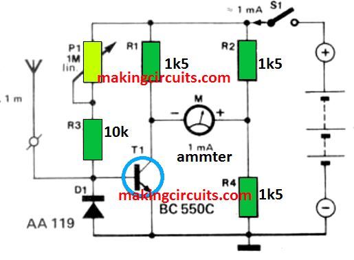
In this field strength meter circuit a BJT transistor is the only active element in the circuit. The transistor here is utilized as a control resistance in one of the arms of a metering bridge. The transistor’s base is connected to the wire or the rod aerial.

The transistor is driven by the increasing HF voltage at the base of the aerial drives. This enables the bridge to bring to equilibrium.

After that, current flows through R2, the mA meter, as well as the collector-emitter junction of the transistor. Before switching on the transmitter, the meter must be brought down to zero with P1.

You'll also like:

  • 1.  How to Measure Thunderstorm Distance using an Electronic Circuit
  • 2.  Vehicle Speedometer Circuit for Precise Speed Measurements
  • 3.  How to Build a 1.5 V Inductance Meter Circuit
  • 4.  Noise Level Meter Circuit
  • 5.  2 Simple Accurate Capacitance Meter Circuits
  • 6.  Adjustable Continuity Tester Circuit

Tagged With: BJT, Field, Meter, Strength

About Admin

Hey friends, Thanks a bunch for stopping by this site! I am an engineer with a Bachelor of Engineering in Electronics and Telecommunication.

One of my passions is gathering information from all sorts of electronics books and tutorials. I then take that information and compile it into a language that is super easy to understand.

My goal is to make those complex electronics circuit concepts and technical terms much more accessible for all the new and budding electronics engineers out there.

I can also design customized circuit diagrams as required by the users.

If you have any questions related to this field, please do not hesitate to drop a comment!

I am always here and ready to help you out with any queries you might have. I cannot wait to hear from you!

Reader Interactions

Leave a Reply Cancel reply

Your email address will not be published. Required fields are marked *

Primary Sidebar

Categories

  • 3 Phase
  • 8051 Microcontroller
  • Amplifier Circuits
  • Arduino
  • Audio and Amplifier
  • Automation
  • Battery Chargers
  • Bicycle Projects
  • Car and Motorcycle Projects
  • Datasheets
  • DIY Projects
  • Electrical
  • Free Energy
  • Games Projects
  • High Voltage
  • Hobby Projects
  • Household Circuits
  • IC 555 Circuits
  • Ignition Circuits
  • Indicators
  • Infrared
  • Inverter Circuits
  • Lights and Lamps
  • Medical
  • Meter and Tester Circuits
  • Motor Driver
  • New Circuits
  • Oscillators
  • Pets and Pests
  • Power Electronics
  • Power supply
  • Protection Circuits
  • PWM
  • Remote Control
  • Security and Alarm Circuit
  • Sensors and Detectors
  • Signal Processor
  • Solar Controller Circuits
  • SSR
  • Temperature Controller
  • Timer
  • Transformerless
  • Transformers
  • Transistors
  • Transmitters
  • Tutorials
  • UPS
  • Voltage Regulators
  • Water Sensor and Controller
  • Home
  • Privacy Policy
  • Contact
  • Disclaimer
  • Copyright

© 2026 · Making Easy Circuits