This circuit is essentially a straightforward heater or light dimmer controller and it comes packed with components that help suppress radio frequency interference (RFI) and includes a snubber network.
Let us break it down step by step to understand how everything fits together:
Main Components Working
TRIAC (TR1): At the heart of this setup we have a C106B1 TRIAC which acts as the main switching device.
This little guy is capable of controlling the AC power that goes to whatever load you are using, whether that is a heater or a lamp.
DIAC (D1, HT-32): Connected to the gate of the TRIAC, this DIAC is super important because it provides controlled triggering.
This ensures that everything operates smoothly and stably.
Resistors (R1, R2, R3, R4, R5): These resistors play a crucial role in setting the timing and voltage conditions that are necessary for the DIAC and TRIAC to work properly.
Capacitors (C1, C2, C3, C4):
C1 and R2: Together they form a timing circuit that sets up the phase delay for when the TRIAC gets triggered.
C3 and R5: This duo creates a snubber network that helps suppress those pesky voltage spikes and counter-electromotive force (counter-EMF) generated by the load.
C4: This capacitor is specifically designed to suppress any RFI that gets generated when the TRIAC switches on and off.
Inductor (L1): This component adds an extra layer of RFI suppression by filtering out high-frequency noise that could interfere with operation.
Potentiometer (R2): This handy little part allows you to adjust the power level going to the load by changing how the TRIAC gets triggered.
Switch (S1): This is your basic on/off switch for the whole circuit.
How It Works
Phase Control for Power Adjustment
Here is how it all comes together:
The AC mains voltage flows through resistors R2, R3, and capacitor C1.
As this happens... the phase angle of the AC wave gets delayed.
At a specific point in the AC cycle the DIAC triggers the TRIAC.
You can adjust this firing angle using R2 which controls how much effective power gets delivered to your load.
RFI Suppression
Now let us talk about how it handles interference:
The snubber network made up of R5 and C3 works hard to reduce counter-EMF generated by inductive loads like motors or heaters with coils.
This protects the TRIAC from damage and minimizes any noise.
Capacitor C4 helps filter out high-frequency noise even further, giving you better RFI suppression.
Load Isolation and Filtering
Inductor L1 acts like a choke in this setup.
It filters out any leftover noise and enhances the overall stability of the circuit when dealing with inductive or resistive loads.
Advantages of the Circuit
Smooth Dimming or Heating Control: Thanks to adjustable phase control you can achieve precise control over power levels.
Protection for Components: The snubber network does a great job of protecting the TRIAC from those nasty voltage spikes caused by counter-EMF.
RFI Reduction: With multiple suppression elements like L1, C4, R5, and C3 working together, this circuit effectively prevents interference with nearby electronic devices.
Notes: The Diac (D1) fires and generates a trigger pulse for the Triac's gate (TR1) as soon as the voltage surrounding C2 rises beyond approximately 30 volts (in the course of any phase cycle).
The load connected to SO1 receives the full AC line voltage as a result of the Triac turning on.
Modifying the potentiometer R2 alters the average amount of energy delivered to the heater load by changing the phase (timing) of the trigger pulses delivered to the Triac.
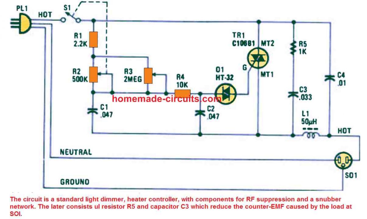
In order to safeguard the Triac from inverse EMF voltage spikes caused by inductive loads, resistor R5 and capacitor C3 function as a snubber circuit across the Triac each time it is turned off.
The 50 µH choke inductor L1 and capacitor C4 are set up as an electromagnetic suppression filter, which makes it possible to remove the radio frequency noise that these kinds of light dimmers or heater controllers frequently produce.
In addition to helping the user make certain that the power to the heater always begins at the lowest power as long as R2 is adjusted to the lowest position and that the heater receives the highest power whenever R2 is adjusted to its highest setting, the preset R3 also modifies the lowest starting range of the heater temperature.
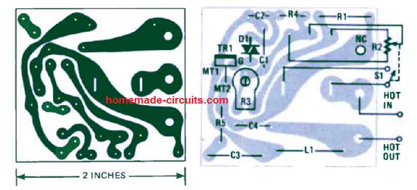
PCB Design
Leave a Reply