In this post we have a high power solar LED garden light circuit which works with a solar panel, to charge a battery during daytime and switch the LED on at night and off in the morning automatically. Now let’s go through how this thing works step by step in a crude way.
How This High Power Solar LED Garden Light Circuit Works:
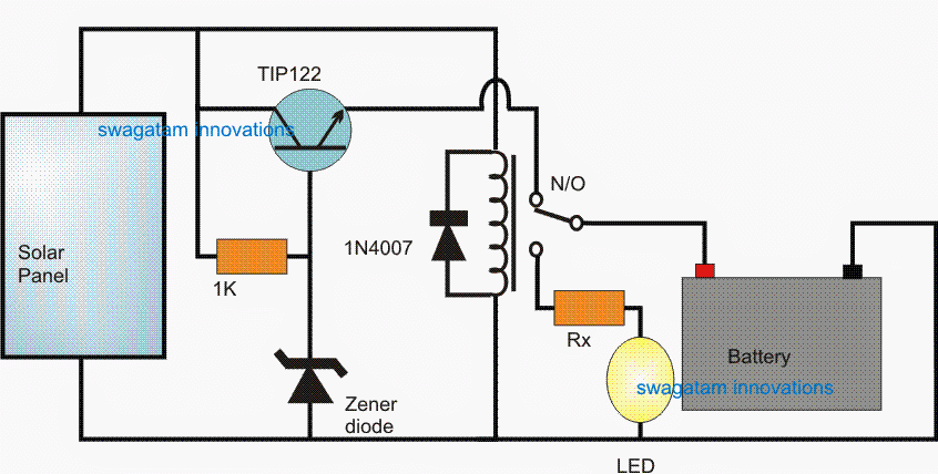
Solar Panel Charges Battery During Day
Ok, so first we have the solar panel at the input. It takes sunlight and produces DC voltage.
This voltage is used for charging the battery. The battery stores the energy so we can use it later at night.
Transistor (TIP122) Controls the Relay
Now we see this TIP122 transistor sitting in the middle. It acts like a switch but works electronically.
A 1K resistor is connected to its base which decides when it should turn on.
Zener Diode Detects Solar Panel Voltage
The Zener diode here is important. It is set to a specific voltage (say 12V or so).
When the sun is shining then solar panel voltage is high and the Zener diode keeps the transistor turned ON.
Relay Works as an Automatic Day-Night Switch
Now when the transistor is ON then it also powers the relay coil.
The relay is normally open (N/O) meaning when it is ON, it keeps the LED disconnected from the battery. But in this situation it charges the battery through the solar paanel voltage passing through th N/O contacys to the battery.
So in the daytime, the battery charges, and LED stays OFF because the relay is activated at its N/O contact.
What Happens at Night?
Ok, now the sun goes down and the solar panel stops producing voltage.
The Zener diode stops conducting so the transistor turns OFF.
When the transistor is OFF then relay deactivates and shifts from the N/O contact to N/C contacts.
Battery Now Powers the LED
Since the relay is now shifted to its N/C contacts, the battery gets directly connected to the high-power LED through the common pole of the relay.
The Rx resistor ensures that only the right amount of current goes to the LED, so it does not burn out.
The LED now lights up and stays ON all night, using the battery’s stored power.
Diode 1N4007 Protects the Relay Coil
This small 1N4007 diode is placed across the relay coil.
It prevents sudden voltage spikes when the relay switches, so nothing gets damaged.
How to Build This High Power Solar LED Garden Light – Step by Step
Ok so now we will see how to build this high power solar LED light in a simple way, step by step. We will start from collecting parts then wiring them and finally testing the circuit. Alright let us begin then!
Step 1: Collect the Required Parts
First, we need to gather all the parts. Here’s what we need:
| Component | Specification | Quantity |
|---|---|---|
| Solar Panel | 12V, 10W (or higher) | 1 |
| Battery | 12V, 7Ah (or higher) | 1 |
| High Power LED | 10W – 50W (as per need) | 1 |
| TIP122 Transistor | NPN Darlington | 1 |
| Zener Diode | 12V, 1W | 1 |
| Resistor | 1K, 1/4W | 1 |
| Relay | 12V, SPDT (Single Pole Double Throw) | 1 |
| 1N4007 Diode | General Purpose | 1 |
| Rx Resistor | As per LED current | 1 |
Alright we have all parts ready, now we move to wiring.
Step 2: Preparing the Circuit Board
Take a small PCB (Printed Circuit Board) or general-purpose board.
Place the TIP122 transistor in the middle because it is the main switching part.
Keep space for the relay near it since they work together.
Make sure there is enough space for wires from the solar panel, battery, and LED.
Now we are ready to do connections!
Step 3: Connecting the Solar Panel and Battery
First connect the solar panel.
The positive terminal (+) goes to the battery’s positive terminal (+) through the circuit.
The negative terminal (-) goes directly to the negative of the battery and circuit ground.
Now connect the battery properly.
Positive of battery → Goes to relay and LED circuit.
Negative of battery → Connect to common ground of all parts.
Step 4: Wiring the TIP122 Transistor and Zener Diode
Connect the Zener diode.
One side to the base of TIP122 transistor.
The other side to ground.
Connect the 1K resistor between the Zener diode and solar panel positive.
This setup makes sure that the transistor turns ON when solar voltage is high.
Step 5: Connecting the Relay
Relay coil connection:
One side to collector of TIP122.
Other side to positive of battery.
Diode 1N4007 across relay coil:
Cathode (white line) to battery positive, Anode to transistor collector.
This protects from voltage spikes.
Now when the transistor turns ON, then relay gets activated.
Step 6: Connecting the LED and Rx Resistor
LED Positive → Connect to battery positive.
LED Negative → Goes to N/O (Normally Open) contact of the relay.
Rx Resistor in series with LED → Ensures correct current supply.
The relay will connect the LED to the battery only when it deactivates (at night).
Step 7: Final Checking and Testing
Check All Connections:
Make sure positive and negative connections are correct.
Ensure no loose wires.
Daytime Test:
Put the circuit under sunlight.
The relay should turn ON, then LED should stay OFF.
Nighttime Test:
Cover the solar panel completely (simulate night).
The relay should turn OFF, then LED should turn ON using battery power.
If everything works fine, you are done!
Final Touches & Installation
Use a proper heatsink for the high-power LED to prevent overheating.
Mount the solar panel in a place where it gets maximum sunlight.
Keep the battery in a shaded area to protect it from excessive heat.
Use waterproof casing for all components to make the circuit last longer outdoors.
Conclusion: so What We Achieved?
Daytime: Solar panel charges the battery and LED stays OFF.
Nighttime: Relay turns OFF and battery powers the LED and light turns ON automatically.
No manual work needed! This circuit will work every day on its own.
Ok so now you have a fully working high power LED automatic solar garden light! If you follow all steps properly, this should work great. Let me know if you need any more details.
Leave a Reply