This intricately designed high precision electronic stethoscope circuit comprises two essential components: the microphone and the amplifier. Let us commence with the electronic segment.
Circuit Description
We initiate with a preamplifier constructed around IC1A, an integrated circuit serving as an amplifier. The amplification level can be fine-tuned by adjusting the two resistors flanking the slider of potentiometer P1.
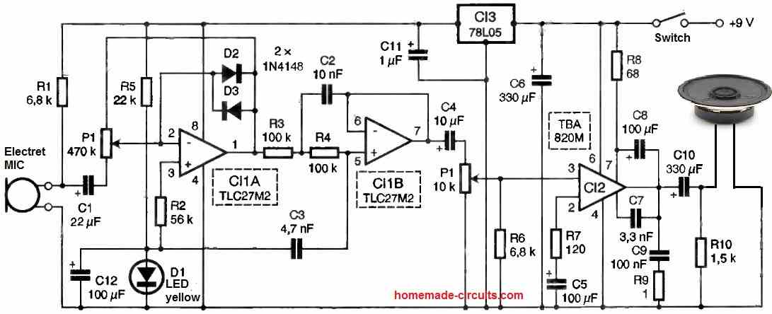
The microphone, an electret variant, undergoes polarization via resistor R1. Capacitor C1 possesses a relatively high value. Considering that heart sounds exhibit a comparatively low frequency and possess an impulsive nature.
To constrain the output voltage amplitude and safeguard against saturation resulting from an impact on the microphone, two diodes, namely D2 and D3, are employed.
A 9V battery serves as the power source for the circuit, while a 5V regulator furnishes power to the dual operational amplifier IC1 and the microphone, ensuring a sound-independent voltage level.
A yellow light-emitting diode (LED) establishes the biasing of the circuit, and capacitor C12 diminishes the internal resistance of this component.
IC1B assumes the role of a second-order low-pass filter configured in a Sallen and Key arrangement. The cutoff frequency, prioritizing lower frequencies, stands at 200 Hz.
For experimental purposes, it is feasible to modify the cutoff frequency to enable listening to sounds beyond the predetermined 200 Hz range.
The biasing of this stage is directly achieved through the output of IC1A, with resistors R3 and R4 facilitating a direct connection for direct current (DC). IC1, an UNCMOS amplifier characterized by an almost negligible bias current, ensures that no voltage drop occurs across these two resistors.
Following the filter, a power amplifier employing a TBA820M is implemented, utilizing a conventional circuit encompassing the customary assortment of resistors.
R6 aids in maintaining input bias in the event of poor contact with the potentiometer slider. The potentiometer itself should be of the logarithmic variant.
The stereo output jack's two contacts are connected in parallel, facilitating mono headphone listening with both earphones linked concurrently.
Resistor R10 is employed to charge capacitor C10. In the event of connecting headphones already positioned on the ears, no charge will accumulate in the earphones, thereby eliminating any detrimental or unpleasant noise.
Although the microphone is of the electret type, its efficiency in capturing body sounds is inadequate. Hence, we have modified it to alter the active surface of the membrane.
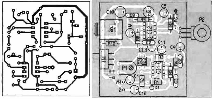
PCB Designs
Dear Admin,
Are you reachable by email ?
If yes, please reply directly via email with the subject
“High Precision Electronic Stethoscope Circuit”
Hi AB,
Please feel free to ask your question here, I will surely answer…