The sensing of the heart pulses is actually produced by two IR photo diodes one being the transmitter of IR while the other acceptor.
The IR rays thrown by the transmitter diode is shown from the finger tip blood content of a person and is obtained by the receiver diode. The strength of the shown rays differ at a proportion driven by the heart pumping rate and by the change in the oxygenated blood levels inside the blood content.
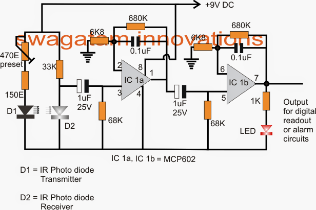
The felt signals from the infrared diodes is prepared by the presented opamp phases which can be actually a number of similar active low pass filter circuits established to cut-off at around 2.5 Hz. This means that the highest accessible heart rate measurement could be limited to about 150 bpm.
We utilize the IC MCP602 for the processing by means of IC1a and IC1b in the offered heart rate sensor and processor design. The IC is a dual opamp designed by microchip.
It's built to work with single supplies therefore turns into incredibly beneficial for the mentioned circuit which can be meant to function from a single 9V cell. This actually also signifies that the output of the opamp have the ability to generate a full positive to negative voltage swings in accordance with the felt heart rate signals from the IR diodes.
Considering that the ambient circumstances might be polluted with a good amount of stray signals, the opamps has to be immunized against all such spurious electrical disturbances, consequently obstructing capacitors by means of the demonstrated 1uF capacitors are placed at the inputs of each opamps.
The first opamp is placed to deliver a gain of 101, the second one being similar to the first IC1a configuration is also set at 101 gain, in spite of this that shows that the overall or the concluding gain of the circuit at the output is offered at an impressive 101 x 101 = 10201, such high gain guarantees a perfect sensing and developing of the incredibly poor and unclear input heart rate pulses provided from the IR diodes.
An LED can be watched connected across the output of the second IC1b opamp which blinks as a reaction to the acquired heart rate pulses from the IR diode stage.
The application in this article is for reference design purposes only and is not meant for any life-saving or medical-monitoring use.
Tips on how to Begin the Heart rate sensor circuit
Starting the suggested heart rate sensor, processor is in fact very simple.
Of course we all will realize that the difference between the oxygenated blood and de-oxygenated blood might be barely distinguishable and need significant accuracy in all values to be able to permit the processor to judge the subtle differences within the blood stream and yet have the ability to change into a swinging voltage change at the output.
To be able to make sure a completely optimized IR beams from the IR Tx diode, the current by means of thus making it confined to a well determined proportion such that the oxygenated blood provides a comparatively higher resistance for the rays to go through however permits fairly lower amount of resistance for the rays during the deoxygenated state of the blood making it simpler for the opamp to distinguish between the beating heart pulses.
This is just performed by modifying the presented 470 ohm preset.
Maintain your index finger tip over the D1/D2 pair, turn on power and keep modifying the preset until the LED at the output starts to develop an individual flashing impact.
Seal of the preset once this is accomplished.
Positioning arrangement of the index finger over the enclosed photo diodes
It might be performed by soldering the diodes over the PCB at certain measured distance apart that evolves into just good for the index finger tip to cover the radiating tips of diodes totally.
For an optimal reply the diodes needs to be enclosed inside an appropriately sized opaque plastic pipes, as demonstrated in the following figure:

In the next submit we'll understand a basic heart rate monitor and alarm circuit specially created for the elderly citizens for keeping a track of their heart critical rate.
Leave a Reply