In this post we are looking at one more unique solar power design and this one is about how we can correctly calculate and configure a simple setup that can be used for generating electricity from solar panels. Then we can use this system for houses that are located in faraway remote areas where regular grid electricity is not available or it can also be used by anybody who wants to go completely off the grid and use only solar power for electricity.
This idea was requested by one of the dedicated readers of this blog.
Technical Details
Right, so now I am quite sure that you must already have a circuit diagram for this. But then, when I was checking your blog, I got a bit confused and lost. I could not really decide which circuit would be the best fit for what I need.
So now I am just putting my requirement here to make sure I have understood things correctly.
(Just to let you know, this is only my first trial project where I am trying to explore and learn about this field. You can think of me as someone who knows absolutely nothing about electrical concepts.)
Now my main goal is to make full use of solar power as much as possible and bring my electricity bill down to the lowest possible level. (I am from India so you can guess how painful the electricity bills are here.) So, in a way I am thinking about setting up a completely solar-powered lighting system for my home.
So, if there is enough sunlight then I do not want any artificial lights to turn on.
But then if the sunlight starts getting weak and goes below a certain level, then I want my lights to turn on automatically.
Then at bedtime, I would want to switch them off myself.
My present lighting system which I am planning to replace with this solar-powered system consists of two regular tube lights (36W/880 8000K) and four CFLs (8W each).
Now my plan is to fully replicate this entire setup but instead of tube lights and CFLs I want to use LEDs that run completely on solar power.
Now as I said before, I am totally blank when it comes to electrical stuff. So I also need some guidance regarding how much this whole setup will cost me.
Design Explanation
Ok now let us start calculating everything step by step.
So first we know that we have:
36W x 2 (for the tube lights)
8W x 4 (for the CFLs)
Now, adding these together gives us a total power requirement of:
36 x 2 + 8 x 4 = 80 watts
Now since these lights work on our regular 220V mains power so we will then need an inverter to convert the solar panel voltage into the correct form so that these lights can be powered.
Then because an inverter cannot work without a battery, so we will need a battery as well. So if we assume that we will use a 12V battery then we can move forward with the following calculations:
Step 1: Calculating Total Power Requirement
The total power consumption is 80 watts.
Now if we assume that the lights will be used from morning 6 AM to evening 6 PM then the total hours of operation will be 12 hours.
So total energy required per day =
80W x 12 hours = 960 watt-hours
This means our solar panel should generate at least 960 watt-hours of power every day to meet this demand.
Step 2: Calculating Solar Panel Size
Now we cannot assume that we will get full sunlight for 12 hours straight every day. So to be on the safer side, let us assume that we get strong sunlight only for about 8 hours per day.
Now we divide our total energy requirement by the available sunlight hours:
960 watt-hours ÷ 8 hours = 120 watts
So our solar panel must be at least 120 watts rated.
If we pick a solar panel voltage of 18V then we can calculate the required current:
120W ÷ 18V = 6.66A
So we can just round this off to 7A, meaning our solar panel should be 120W, 18V, 7A rated.
Step 3: Calculating Battery Capacity
Now we need to calculate what battery size will be enough for this setup.
Again we already calculated the total daily power requirement:
960 watt-hours
Now if we are using a 12V battery then we divide:
960 watt-hours ÷ 12V = 80 Ah
So,the closest practical battery size would be 12V 100Ah. This should be enough to give us full 12-hour backup for the lighting system.
Step 4: Choosing the Charge Controller
Now we need to select the right solar charge controller to charge the battery.
Since we assumed that the battery will take about 8 hours to charge then the charging rate should be around 8% of the battery capacity:
100Ah x 8% = 8A
So the charge controller should be rated for at least 7A to safely charge the battery without any issues.
Alternative Setup Without Battery
Now in case we feel that the battery is not needed and we just want to run the inverter directly from the solar panel then that is also possible.
For this we can use a solar panel voltage regulator circuit which will make sure that the voltage going into the inverter remains stable and does not fluctuate too much.
In this case we can also add a manual switch that will allow us to choose between:
Battery charging mode – Then when we want to store solar energy in the battery.
Direct inverter mode – Then, when we want to power the inverter directly from the solar panel without the battery.
Since the regulator in the aforementioned scenario must provide between 7 and 10 amps of current, an LM396 or LM196 must be utilized in the charger stage.
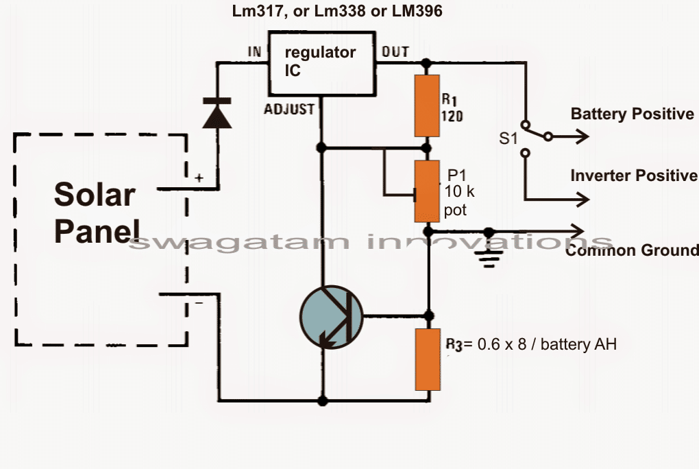
Building the Solar Regulator Circuit
Alright so now we will explain how to build the LM338 or LM396 voltage regulator circuit step by step. These are high-power adjustable voltage regulators so we must be careful while handling them, as they deal with high current and can get hot. First before we start assembling anything, we will gather all the necessary components and make sure everything is working fine.
Step 1: Collect All Required Parts
First we will need these components:
Main Regulator IC:
LM338 or LM396 (this is the main voltage regulator IC, capable of handling high current)
Resistors:
R1 = 240 ohms (this is the standard resistor for setting the output voltage)
R2 = Variable resistor (potentiometer) 5K (this will be used to adjust the output voltage)
Capacitors:
C1 = 0.1µF ceramic (this is needed at the input to filter any noise)
C2 = 10µF electrolytic (this stabilizes the regulator and improves transient response)
C3 = 1µF electrolytic (this is connected at the output for better regulation)
Diodes:
D1, D2 = 1N5408 (these are protection diodes to prevent reverse voltage damage)
Heatsink:
Large aluminum heatsink (this is necessary because LM338 or LM396 can get very hot when delivering high current)
Step 2: Fix the LM338/LM396 on a Heatsink
Since this IC will dissipate a lot of heat when it is regulating high power, we must attach it to a large heatsink. If we do not, then it will quickly overheat and shut down. We can then apply thermal paste between the IC body and the heatsink to improve heat transfer.
Step 3: Connect the Resistors and Potentiometer
Now we will take R1 (240 ohms) and connect it between the output pin (Vout) and the adjustment pin (Adj) of the regulator. Then we will take R2 (5K pot) and connect one end to the adjustment pin and the other end to ground. This setup will allow us to vary the output voltage by adjusting the potentiometer.
Step 4: Connect the Capacitors
Now, we will add the capacitors:
C1 (0.1µF) will be connected between the input pin (Vin) and ground to filter any high-frequency noise.
C2 (10µF) will also be connected at the input side to improve stability.
C3 (1µF) will be connected at the output to ensure smooth voltage regulation and reduce ripples.
Step 5: Connect the Diodes for Protection
We must add D1 and D2 (1N5408 diodes) to protect the IC from reverse voltage spikes.
D1 will be connected between Vout and Vin, with its cathode to Vin and anode to Vout.
D2 will be connected between Adj and Vout with its cathode to Vout and anode to Adj.
These diodes will ensure that the regulator does not get damaged due to sudden changes in load conditions.
Step 6: Connect the Input Power
Now we will connect the input voltage source (DC supply, like 12V to 35V battery or adapter) to the regulator. The positive terminal of the power source will go to the Vin pin of the regulator and the negative terminal will be connected to ground.
Step 7: Adjust and Check Output Voltage
Now we will take a multimeter and connect it to the Vout pin and ground. We will then slowly adjust the potentiometer (R2) and check how the output voltage changes. It should smoothly vary within the designed range. If the voltage is not stable then we must check all connections.
Step 8: Load Testing
Once we have confirmed that the voltage is adjustable and stable, we will connect a small DC load (like a 12V bulb or small motor) to test how well the circuit supplies power.
If the voltage remains stable under load then everything is working fine.
If the voltage drops suddenly then there may be a wiring issue, or the heatsink may not be properly dissipating heat.
Step 9: Final Assembly and Safety Precautions
Then if everything is working perfectly we will mount the circuit inside a suitable enclosure making sure that:
The heatsink is properly exposed to air so that heat can dissipate easily.
All high-power connections are insulated to prevent short circuits.
We must never touch the metal part of the IC or the heatsink while it is running, as it may get extremely hot.
Finished! We Have Built the Voltage Regulator Circuit!
That is all! Now we have successfully built a high-current adjustable voltage regulator using LM338 or LM396. This circuit can be used to power different DC loads, charge batteries or provide a steady voltage for other electronic circuits.
Inverter Circuit
The following straightforward inverter circuit could be set up with the aforementioned solar panel regulator, and it would be more than sufficient to power the desired lighting using either the battery or the attached solar panel.
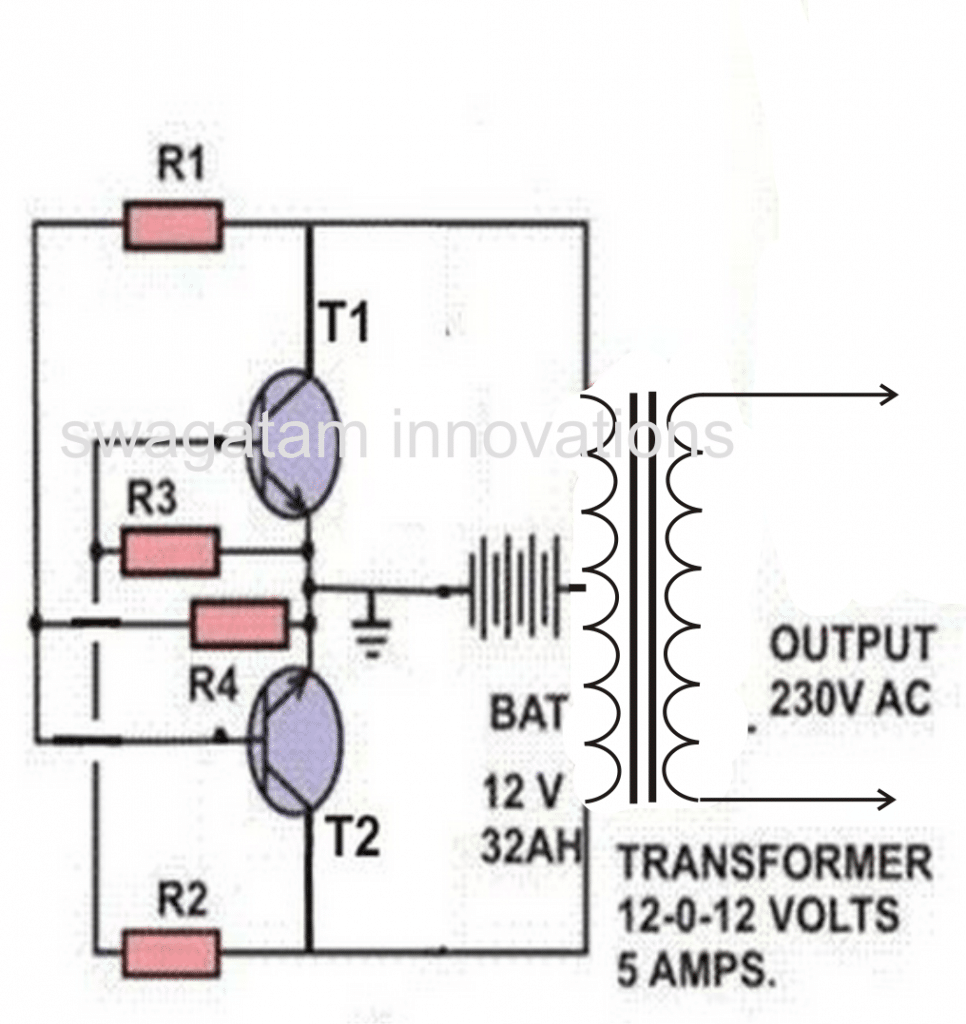
Parts list for the above inverter circuit: R1, R2 = 100 ohm, 10 watt
R3, R4 = 15 ohm 10 watt
T1, T2 = TIP35 on heatsinks
How We Will Build This Inverter Circuit Step by Step
Alright, so now we are going to put together this inverter circuit step by step but we must be very careful because it is using high power parts and we do not want anything to go wrong. So first, before we even start fixing anything, we will gather all the necessary parts and check if everything is good.
Step 1: Collect All Required Parts
First we need to get these components ready:
Resistors:
R1, R2 = 100 ohm, 10 watt (these will go to the base of the transistors to limit base current)
R3, R4 = 15 ohm, 10 watt (these will go between base and collector of each transistor to give proper bias and oscillation)
Transistors:
T1, T2 = TIP35 (these are the power devices that will switch ON and OFF to make the circuit work)
Battery:
12V, 32AH (this will supply the DC power for the circuit)
Transformer:
12-0-12V, 5 Amps (this will take the switching DC and step it up to 230V AC)
Now we will check all these parts one by one, test them if needed and confirm that nothing is faulty. Only then we will move to the next step.
Step 2: Fix the Transistors on Heatsinks
Now since these TIP35 transistors will get quite hot then we must fix them tightly on good-sized heatsinks. We cannot just leave them open or they will burn out. Also we will apply thermal paste in between the transistor body and the heatsink so that heat can transfer properly. This is important, or else overheating will happen.
Step 3: Connect the Resistors
So now we will take R1 and R2 and connect them to the base of each transistor in series. This will make sure the base current does not become too high otherwise the transistors can get damaged. After this we will connect R3 and R4 from the collector to the base of each transistor. This will help in feedback and keep the oscillation working correctly.
Step 4: Wiring the Transformer
Now we will take the primary side of the transformer which is the 12-0-12V side. The middle wire of this (center tap) must be directly connected to the positive terminal of the battery. Then the remaining two ends of the transformer winding will go to the collectors of both transistors T1 and T2. This will complete the power switching section.
Step 5: Connect the Battery
Next we will take the negative terminal of the battery and connect it to the common ground of the circuit. The positive terminal was already connected to the transformer center tap so there is nothing else to do for that. Now the basic circuit wiring is complete.
Step 6: Switch ON and Check if It Works
Now before switching ON we must double-check all connections. Then if anything is loose or wrong, we should fix it now. Once we are sure everything is correct we will switch ON the battery supply. Then the transistors should start switching, and then the transformer should generate AC voltage at its secondary winding.
Now we will take a multimeter and check the voltage at the output of the transformer. Then it should show around 230V AC. If not then there is some problem, and then we will need to check the wiring again.
Step 7: Load Testing
Once we are sure that the output is 230V AC then we will take a small AC appliance, such as a 60W bulb, and connect it to the output terminals. Then if everything is working fine then the bulb should glow steadily. Then if the bulb is flickering or not lighting up, then we have to check for loose wires, incorrect polarity or maybe some faulty component.
Step 8: Final Assembly and Safety
Then if everything is working properly then we will now put the whole inverter circuit inside a suitable case or enclosure. But we must make sure that all high-voltage wires are properly insulated otherwise then touching them by mistake can give us a dangerous shock. Once it is enclosed, then we must never touch the open wires.
Done! We Have Built Our Inverter!
That is all! Now we have successfully built a simple inverter circuit that takes 12V DC from a battery and converts it into 230V AC. This setup is very useful for running small appliances whenever there is a power cut.
The request's final sentence recommends designing an LED variant to upgrade and replace the current CFL fluorescent lights. As seen below, the same thing could possibly be accomplished by just removing the battery and inverter and connecting the LEDs to the solar regulator output:

Remember It is crucial to hook up and make the adapter's negative common ground line with the solar panel's negative line.
Conclusion
So now we have gone through all the steps to design a simple solar-powered lighting system. We saw how to calculate the solar panel size, battery size, inverter requirement, and charge controller rating.
This same method can be used for any other off-grid solar power setup, whether for rural areas, remote houses or just for saving electricity costs in cities.
Then if we need different voltage or current ratings then we can just adjust the above calculations accordingly to get the correct values.
Leave a Reply