In this post we are going to understand how crystal oscillator circuit works and we will be constructing one, which can generate frequency at Mega-hertz range.
In this digital world, all digital processors are virtually dead without clock signal. Today’s processors does complicated functions like solving math problems, cryptography, information transfer between processors, communicating with input and output devices etc. To accomplish any basic operation we need clock signal, the clock signals are like heart of the processors, whether it may be a latest core i7 processor or a basic microcontroller.
These microcontrollers and microprocessor need stable high frequency clock signal to operate consistently. To achieve this we are going with crystal oscillator which can attain consistent high frequency and it is less susceptible to temperature changes. Before the implementation of crystal oscillators, LC and RC type of oscillators were used and those were not good at generating more than 1 MHz signal.
Let’s see how a crystal oscillator works.
It works on the principle of inverse pizeo-electric effect. When certain type of material is mechanically stressed it produces voltage proportional to the applied stress, it is called piezo electric effect. The inverse process is utilized in crystal oscillator. When the material is applied with electricity the material begin to oscillate.
The oscillation of the crystal material is very consistent, that’s why our wrist watches or wall clock utilizes quartz crystal for ticking each second.
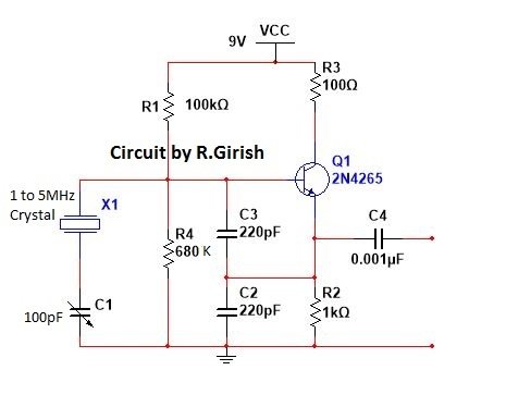
The circuit:
The circuit is configured as common collector amplifier. The two resistors R1 and R4 providenecessary bias for the transistor. The resistor at emitter R2 sets the output voltage level.
The 2N4265 transistor may be replaced with any general purpose NPN transistor. But make sure it can handle at MHz frequency range,which can be found in data sheet.
The C1 and C3 are used to limit the gain of the transistor. This will limit the output amplitude and reduce power dissipation in the crystal. If the power dissipation in the crystal is high, the crystal might get damaged due to excess mechanical vibration.
Different Types of Crystal Oscillators
Since crystals comprise carefully cut piezoelectric quartz crystals that work like highly accurate electromechanical resonators or tuned circuits, crystal oscillator circuits deliver reliable, consistent frequencies.
These designs use crystals with Qs of around 100,000, and these can give up to 1000 times more frequency stability than ordinary inductive-capacitive (LC) tank-circuit oscillators.
The mechanical parameters of a piezoelectric crystal define its working frequency, which ranges from a few kHz to 100 MHz. The crystal could be sliced to give resonant functioning in either series or parallel.
At resonance, series-mode crystals exhibit a low impedance, but parallel-mode crystals have a high impedance. A realistic circuit for a crystal oscillator developed for a parallel -mode crystal is shown below.

The circuit is a Pierce oscillator, and it will work with almost all parallel-mode crystals from 100 kHz to 5 MHz without any modifications.
An alternate 100-kHz oscillator for a series-mode crystal is shown in the following image.

A Colpit oscillator is what it's called. The tank circuit, which consists of L1, Cl, and C2, is tuned to exactly the same frequency as the crystal.
Nevertheless , if you want to use different crystal frequencies, you'll have to adjust the tank circuit parameters. The design for an usable two-transistor oscillator that works with almost all 50 kHz to 10 MHz series-resonant crystals is shown in the following figure.

Q1 is used as a common base amplifier, while Q2 is used as an emitter follower in this circuit. Using C2 and the series-resonant crystal, the output signal (through Q2's emitter) is returned to the input (Q1's emitter).
This oscillator circuit is flexible enough to function with even a low-cost, inferior crystal. As a result, the circuit can work as the crucial stage of a basic crystal tester.
Leave a Reply