In this post we comprehensively discuss how to design and calculate your own ferrite transformer by suitably calculating the various necessary parameters such as primary turns, Bmax of the ferrite core, the secondary turns, the core dimensions, auxiliary winding and other related variables.
For transformer model, the distinction among a push-pull and a full-bridge transformer meant for similar voltage and power will likely be that the push-pull transformer will demand a center tap, which means it will need two times the amount of primary turns as the full-bridge transformer.
Calculation of required turns is in fact pretty basic I’ll clarify this here.
For description, I’ll work with an illustration and deal with calculation process.
For example let's imagine the ferrite transformer is intended for a 250W inverter. The chosen topology is push-pull. The power supply is a 12V battery. Output voltage of the DC-DC converter stage is going to be 310V.
Switching frequency is 50kHz. The chosen core is ETD39. Keep in mind that the output of the transformer will probably be high frequency AC (50kHz square wave in this instance). As i make reference to an output of high voltage DC (eg 310VDC mentioned previously), this is actually the DC output attained following rectification (making use of ultrafast recovery diodes set up as bridge rectifier) and filtering (using LC filter).
In the course of operation, the battery voltage is not going to be fixed at 12V. With higher loads, the voltage is going to be under 12V. With reduced loads and around fully charged battery, the voltage could possibly be greater than 13V. Therefore, it should be considered that the input voltage is not really consistent, rather is varying. In inverters, the battery low-cut is commonly established at 10.5V. Thus, we’ll work with this as our most reasonable input voltage.
Vin(min) = 10.5V
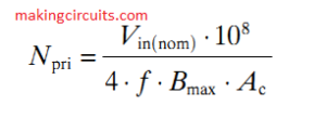
Calculating Primary Turns
The formula for determining the quantity of necessary primary turns is:

For the push-pull transformer, this can be one-half the required range of turns.
N(pri) indicates amount of primary turns; N(sec) signifies amount of secondary turns; N(aux) suggests amount of auxiliary turns and so forth. However just N (with no subscript) describes turn or winding ratio.
For calculating the desired volume of primary turns utilizing the formula, the variables or specifics that must be deemed are:
Vin(nom) - Moderate Input Voltage. We will consider this as 12V. Therefore, Vin(nom) = 12.
f = The working switching frequency in Hertz. Considering that our switching frequency is 50kHz, f = 50000.
B(max) = Maximum flux density in Gauss. Should you be accustomed to applying Tesla or milliTesla (T or mT) for flux density, remember 1T = 104Gauss.
B(max) actually is determined by the design and the transformer cores used. In our designs, we'll typically consider Bmax to stay within the range 1300G to 2000G.
This can be suitable for the majority of transformer cores. In this particular illustration, we may focus on 1500G. Hence Bmax = 1500. Keep in mind that too big a B(max) can cause the transformer to saturate. Far too lower B(max) will likely be not optimally utilizing the core
Ac = Effective Cross-Sectional Area in cm2. You will find these details through the datasheets of the ferrite cores. Ac can also be occasionally known as Ae.
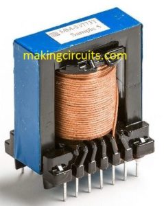
For ETD39, the productive cross-sectional area offered in the datasheet/specification sheet we are talking about is TDK E141.
You may download this from here: Ferrite Core Dimension, the productive cross-sectional area (in the specification pdf, it’s called Ae however as mentioned, it’s one and the same as Ac) which is presented as 125mm^2. Which is equal to 1.25cm^2. So, Ac = 1.25 for ETD39.
Now, we have access to the values of all necessary variables for calculation N(pri) - the amount of necessary primary turns.
Vin(nom) = 12, f = 50000, Bmax = 1500, Ac = 1.25
Inserting these quantities into the formula:
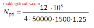
N(pri) = 3.2
We won’t be applying fragmentary winding, therefore we are going to round off N(pri) for the closest whole number, in this particular scenario, let's round it down to 3 turns.
At this point, before we complete this and choose N(pri) = 3, we better make certain that B(max) continues to be within tolerable range. As we’ve lowered the quantity of turns from the calculated number (down to 3.0 from 3.2), B(max) will certainly go higher.
Calculating Maximum Flux Density of Ferrite Core
We at this point have to determine exactly how much B(max) has increased and if that continue to be an appropriate value.
Vin(nom) = 12, f = 50000, N(pri) = 3, Ac = 1.25
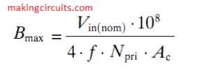

B(max) = 1600
The new figure of B(max) is actually within tolerable range and thus we could continue with N(pri) = 3.
Therefore, we now recognize that for the primary, our transformer will have to have 3 turns + 3 turns.
In just about any design, if you want to modify the values, it is simple to achieve this task. However bear in mind to evaluate that B(max) is appropriately selected.
As an example, suppose due to structure complications, winding 3 turns + 3 turns gets challenging, you could employ 2 turns + 2 turns or 4 turns + 4 turns.
Maximizing number of turns won’t harm - you will merely would be under utilizing the core. However, reducing quantity of turns may raise B(max), therefore just reconfirm to make certain B(max) is appropriately selected. The range we are using for B(max) (1300G to 2000G) is simply an estimation. It will eventually be suitable for most of the cores. Nonetheless, with several cores, it is possible to go bigger in order to decrease the amount of turns.
Planning lower may simply be not utilizing the core optimally, yet may at times be necessary in case number of turns is far too low.
We can start using a fixed B(max) and go on to estimate N(pri) following that. You can even designate a value of N(pri) and subsequently find out if B(max) is acceptable. Otherwise, you can easily maximize or minimize N(pri) as necessary and next see if B(max) was suitable or not, keep repeating this right up until you obtain an acceptable end result.
For instance, you might have fixed N(pri) = 2 and determined B(max) and determined that this had been way too high. Thus, you place N(pri) = 3 and determined B(max) and realized that it was alright. Or perhaps you could have began with N(pri) = 4 and worked out B(max) and made a decision that it was way too small. Therefore, you fixed N(pri) = 3 and computed B(max) and opted it absolutely was good.
At this point it’s time to proceed on to the secondary. The output of our DC-DC converter is 310V. Therefore, the transformer output should be 310V whatsoever input voltages, through all the way upward from 13.5V to all the way lower to 10.5V.
Adding a Feedback
Obviously, feedback is going to be integrated to maintain the output voltage predetermined despite having line and load disparities - variations as a result of battery voltage changes as well as because of load change. Therefore, some +/- margin has to be left for feedback to be effective. Therefore, we’ll design the transformer with secondary specified at 330V.
Feedback will certainly adapt the voltage needed by transforming the duty cycle of the PWM control signals. Apart from feedback, the accomodated margin additionally makes up for some of the deficits in the converter and so compensates for that voltage drops in various phases - for instance, in the MOSFETs, within the transformer alone, in the output rectifiers, output inductor, etc.
This implies that the output has to be effective at providing 330V with input voltage corresponding to 10.5V as well as input voltage corresponding to 13.5V. For the PWM controller, we are going to consider maximum duty cycle to be 98%. The difference makes for the dead-time.
At minimum input voltage (when Vin = Vinmin), duty cycle will probably be highest. Therefore duty cycle is going to be 98% whenever Vin = 10.5 = Vinmin. At highest duty cycle = 98%, voltage to transformer = 0.98 * 10.5V = 10.29V.
Therefore, voltage ratio (secondary : primary) = 330V : 10.29V = 32.1
Given that voltage ratio (secondary : primary) = 32.1, turns ratio (secondary : primary) also needs to be 32.1 as turns ratio (secondary : primary) = voltage ratio (secondary : primary). Turns ratio is specified by N. Therefore, in our situation, N = 32.1 (We’ve considered N as the ratio secondary : primary).
N(pri) = 3
N(sec) = N x N(pri) = 32.1 x 3 = 96.3
Rounding it of to the closest whole number. N(sec) = 96.
Hence 96 turns will be required for your secondary. Through appropriate execution of feedback, a consistent 310VDC output could be acquired throughout the whole input voltage range of 10.5V to 13.5V.
Here, a very important factor to remember is that despite the fact that We involved 98% as the highest duty cycle, optimum duty cycle practically will likely be smaller because our transformer had been computed to supply 330V output. Within the circuit, the output is going to be 310V, therefore the duty cycle will likely be further lower.
Having said that, the benefit here is that you could ensure that the output will never drop below 330V despite having heavy loads considering that a substantial margin is presented to feedback to establish and sustain the output voltage constant even at high loads.
Calculating Auxiliary Winding
In case any auxiliary winding are demanded, the necessary turns could be quickly determined. I'll demonstrate using an example. Let’s imagine we want an auxiliary winding to offer 19V. We realize that the output 310V is going to be controlled, regardless of the input voltage could be, within the specified range in the beginning (Vin(min) to Vin(max) - 10.5V to 13.5V).
Therefore, the turns ratio for the auxiliary winding could be worked out according to secondary winding. We'll name this turns ratio as NA.
NA = N(sec) / N(aux) = V(sec) / (V(aux) + Vd). Vd is the output diode forward potential drop. We'll imagine in our approval, a schottky rectifier having a Vd = 0.5V is applied.
So, NA = 310V / 19.5V =15.9
N(sec) / N(aux) = NA
N(aux) = N(sec) / NA = 96 / 15.9 = 5.96
Let’s approximate N(aux) to 6 and find out the particular output voltage.
V(sec) / (V(aux) + Vd) = NA = N(sec) / N(aux) = 96 / 6 =16.0
(V(aux) + Vd) = V(sec) / NA = 310V / 16.0 = 19.375V
V(aux) = 19.375V - 0.5V = 18.875V (nearest available value)
We might feel honestly, that is perfect for an auxiliary source. In case within your computations you arrived at a voltage which is too much off the essential target voltage and therefore larger precision is needed, consider V(aux) to be something larger and include a voltage regulator.
As an example, when in our earlier illustration, instead of 18.875V we'd obtained 19.8V yet wanted even more accuracy and reliability, we could've applied 24V or nearby and applied a voltage regulator to provide 19V output.
Therefore, there we certainly have it. Our transformer possesses 3 turns + 3 turns for primary, NINETY-SIX turns for secondary and Six turns for auxiliary.
Here’s our finalized transformer using perfectly calculated winding ratio and ferrite core:

Calculating necessary amount of turns for any ferrite transformer is really a straightforward process and I wish this particular guide allows you to design your ferrite transformer comfortably.
Thank you, it is very informative
Thank you…
Is there a pcb layout for dual rail psu of 2000 watts.
Sorry, I do not have a PCB design for that at the moment…
Exelente muchas gracias muy bien explicado me gusto todo el contenido
Hey Frank, thanks so much for your candid feedback…
Escelente dica
Is power related to frequency, core area, Nprim and N sec and How?
peço desculpa li quase no final, inf a respeito
como calcular trafo de smps ,ótimo, só faltou uma inf referente aos fios, devera ser do tipo litz
motivo a frequência de trabalho
thank you, wires should copper, super enameled type
please give me the formula to calculate the winding cross-section for primary and secondary windings. thank you
Thanks. However nothing has been said about , thickness of prim wire, due to the skin effect, can you refer to/ how to determine this please ? 250W / 10,5 V = 23.81 Amps . Witch wire should i use , please ?
Best regards .
The wire thickness will need to be estimated depending on the current….to avoid skin effect you can use many thin wires in parallel instead of using a single thick wire.
a 4 mm wire thickness should be enough to handle 23 amps
This is a strange article, the title is smps, it actually contains an inverter … ??
Hi, Are you sure is this working? What is size of the wires and way of turn ? And where is ckt ? Why there is hissing sound in the ferrite core ?
Will you plz answer ?
All formulas and the concept are standard and referred from credible sources, so everything above is 100% correct. That said, it is not recommended for newcomers, the constructor must have some level of electronics expertise
How I do this with a two switch forward converter? did see nou so much on internet.
thanks