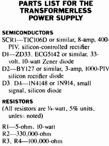
This circuit is a transformerless power supply that utilizes SCRs or silicon-controlled rectifiers to create an adjustable capacitive power supply. Let us learn how this whole thing operates:
Circuit Overview
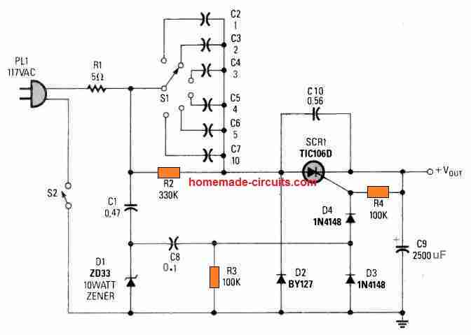
To start with the circuit takes in 117V AC from the mains supply. The first component you encounter is a series capacitor labeled C1 which has a value of 0.47µF.
This capacitor plays the crucial role as it limits the current flowing through by providing capacitive reactance.
Essentially it is the main player in keeping the current in check within this transformerless setup.
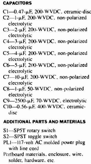
There is also a resistor R1 with the resistance of 5Ω which serves to limit any sudden surge of current when you first power up the circuit. The switch S2 is your go-to for turning the entire circuit on or off.
Next up are the capacitors C2 through C7 which offer various capacitance options that you can select using the rotary switch known as the S1. By tweaking the capacitance values you can adjust how much the current gets sent to the SCR thereby controlling the output voltage.
The AC voltage is then converted to DC by a bridge rectifier consisting of the diodes D2 (BY127) and the D3, D4 (1N4148).
The SCR used here is TIC106D which manages the current flow by allowing only a portion of it to pass through based on its triggering conditions.
To keep things stable and to suppress any voltage spikes there is a capacitor C10 (0.56µF) connected across the SCR.
For safety and functionality there is also a Zener diode D1 (33V, 10W) which clamps the voltage at the gate of the SCR to prevent it from exceeding safe levels.
This ensures that the SCR will only trigger when the voltage hits a certain threshold. the R2 (330kΩ) and R3 (100kΩ) work together to form the voltage divider network that helps set this triggering point for the SCR.
Meanwhile R4 (100kΩ) keeps everything stable by providing the pathway for what is known as holding current.
The output from this circuit gets smoothed out by capacitor C9 (2500µF) which helps convert that pulsating DC into a steady output voltage. The actual output voltage can be adjusted based on which capacitors you have selected in that voltage selection area.
How It Works
Now let us talk about how this whole thing functions. The series capacitor C1 restricts the AC current that enters the circuit based on its reactance formula:
Xc = 1 / (2πfC).
The rotary switch S1 allows for further adjustments in current by selecting additional capacitance values, which impacts both charging and triggering conditions.
The SCR will only trigger when there is enough DC voltage at its gate, which is determined by resistors R2 and R3 along with Zener diode D1.
Once that voltage reaches what we call the Zener breakdown level, the SCR starts conducting and allows current to flow out to where it needs to go.
By altering the capacitance with switch S1, you indirectly control how much current and voltage get delivered at the output.
The big electrolytic capacitor C9 does an excellent job of filtering that rectified DC to minimize ripple and stabilize everything.
Applications
This transformerless power supply design is compact and works well for low-power applications where being isolated from mains power is not super critical. It can be handy for powering small electronic circuits or even as an adjustable DC source for testing things out.
Important Note
Since we are dealing with a transformerless circuit here, it does not provide electrical isolation from mains supply voltages.
This means there are potential hazards involved. Therefore it is really important to exercise caution while handling or testing this circuit!
There are quite a few readily available electrical components that make up this SCR-based high current transformerless power supply.
By turning the rotary switch S1, the amount of output voltage (as well as the possible current level given in Table I) can be changed.
Table#1
| Capacitance (µF) | LOAD 100 Ohms (Vout) | LOAD 100 Ohms (Current mA) | LOAD 200 Ohms (Vout) | LOAD 200 Ohms (Current mA) | LOAD 1000 Ohms (Vout) | LOAD 1000 Ohms (Current mA) |
|---|---|---|---|---|---|---|
| 1 | 3.2 | 31 | 6.0 | 29 | 25 | 24 |
| 2 | 6.4 | 61 | 11.2 | 54 | 41 | 41 |
| 3 | 9.0 | 87 | 16.1 | 78 | 52 | 52 |
| 4 | 11.8 | 113 | 20.7 | 100 | 61 | 61 |
| 5 | 15.5 | 147 | 24.7 | 120 | 67 | 67 |
| 6 | 17.8 | 169 | 28.8 | 144 | 68 | 68 |
| 7 | 18.5 | 176 | 31.9 | 155 | 69.4 | 68 |
| 8 | 20.3 | 195 | 36.8 | 173 | 70 | 71 |
| 9 | 22.8 | 220 | 41.0 | 193 | 71 | 71 |
| 10 | 24.9 | 238 | 42.0 | 200 | 71 | 71 |
| 11 | 27.1 | 259 | 44.9 | 219 | -- | -- |
| 14 | 33.0 | 317 | 52.7 | 257 | -- | -- |
| 20 | 43.5 | 422 | 65.8 | 322 | -- | -- |
Leave a Reply