• Skip to main content
  • Skip to primary sidebar

Making Easy Circuits

Learn and build electronic circuits

You are here: Home / New Circuits / How To Design Simple Power Supply Circuit

How To Design Simple Power Supply Circuit

Last Updated on June 23, 2020 by Admin Leave a Comment

In this post we try to understand how basic power supply circuit works and how to design regulated and unregulated power supply circuits.

UNREGULATED POWER SUPPLY

A single rail power supply is displayed in the diagram below. It has three distinct portions, the power transformer, the full wave bridge rectifier and the filter capacitor.

fig1 19

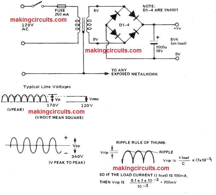
For security, the fuse needs to be set the live wire path to the transformer. The voltages offered are AC voltages measured in Volts RMS. This can be the similar "DC heating" voltage and it is comparable to 0.707Vp.

The output of the transformer is 6V RMS and this also could be the voltage level "on load". Once the transformer is just not loaded this voltage might enhance by around 25%.

The variation amongst the loaded and unloaded output voltage is referred to as the "regulation" of the transformer. Transformers possess power ratings indicated with regards to VA. A 10VA transformer are able to supply 10 watts of power through its secondary output.

The AC voltage through the transformer secondary is full wave rectified through the diode bridge D1 to 4 after which filtered by capacitor C1. Without any load on the power supply the output (DC) voltage will probably be roughly 11V.

However when a resistive load is shown to it, the voltage falls and a ripple voltage shows up, this being a result of the load discharging the capacitor.

REGULATED POWER SUPPLY

Two transistors and a voltage reference enables you to produce a regulated power supply.

Transistor Q1 is employed as the power control element thus needs to be installed on a heat sink. Q2 delivers adverse feedback and thus allows to iron out any alterations at the output caused by varying load conditions or variants in the unregulated rail.

The circuit procedure is as follows. A current passes via Q2 and D5 and so creates a voltage of 5V1 around D5. The base of Q2 is attached to the output with a set of resistors, R2, 3, 4 and RV1.

fig2 8

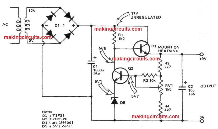
If the output voltage increases, then more current will pass via Q2. This leads to the voltage at the base of Q1 to drop, which often decreases the voltage at the output.

Hence the output voltage is controlled. RV1 is utilized to create the output voltage to +9V. In case the wiper of RV1 need to unintentionally lift off, then the output voltage might immediately increase to that of the unregulated rail.

To avoid this R3 supplies a long lasting DC path to the base of Q2. Capacitor C2 aids you to enhance the regulation once the load conditions change quickly.

You'll also like:

  • 1.  0 – 30 V Regulated Power Supply Circuit
  • 2.  How to make a Temperature Triggered DC Fan Speed Controller Circuit
  • 3.  Build this One Transistor Regulated Power Supply Circuit
  • 4.  How to Calculate SMPS Transformer
  • 5.  LM317 High-Current Bench Power Supply
  • 6.  Simple Dual Power Supply Circuit Without Center Tap

About Admin

Hey friends, Thanks a bunch for stopping by this site! I am an engineer with a Bachelor of Engineering in Electronics and Telecommunication. One of my passions is gathering information from all sorts of electronics books and tutorials. I then take that information and compile it into a language that is super easy to understand. My goal is to make those complex electronics circuit concepts and technical terms much more accessible for all the new and budding electronics engineers out there. I can also design customized circuit diagrams as required by the users.
If you have any questions related to this field, please do not hesitate to drop a comment! I am always here and ready to help you out with any queries you might have. I cannot wait to hear from you!

Reader Interactions

Leave a Reply Cancel reply

Your email address will not be published. Required fields are marked *

Primary Sidebar

Categories

  • 3 Phase (4)
  • 8051 Microcontroller (1)
  • Arduino (11)
  • Audio and Amplifier (102)
  • Automation (8)
  • Battery Chargers (64)
  • Bicycle Projects (4)
  • Car and Motorcycle Projects (39)
  • Datasheets (10)
  • DIY Projects (5)
  • Electrical (15)
  • Free Energy (6)
  • Games Projects (2)
  • High Voltage (14)
  • Hobby Projects (30)
  • Household Circuits (2)
  • IC 555 Circuits (5)
  • Ignition Circuits (2)
  • Indicators (50)
  • Infrared (6)
  • Inverter Circuits (29)
  • Lights and Lamps (97)
  • Medical (8)
  • Meter and Tester Circuits (38)
  • Motor Driver (17)
  • New Circuits (56)
  • Oscillators (30)
  • Pets and Pests (5)
  • Power supply (80)
  • Protection Circuits (25)
  • PWM (9)
  • Remote Control (20)
  • Security and Alarm Circuit (48)
  • Sensors and Detectors (66)
  • Signal Processor (23)
  • Solar Controller Circuits (62)
  • SSR (3)
  • Temperature Controller (20)
  • Timer (25)
  • Transformerless (7)
  • Transmitters (12)
  • Tutorials (45)
  • UPS (2)
  • Voltage Regulators (57)
  • Water Sensor and Controller (29)
  • Home
  • Privacy Policy
  • Contact
  • Disclaimer
  • Copyright

© 2025 · Making Easy Circuits