• Skip to main content
  • Skip to primary sidebar

Making Easy Circuits

Learn and build electronic circuits

You are here: Home / Indicators / How to Make a 4 LED Temperature Indicator Circuit

How to Make a 4 LED Temperature Indicator Circuit

Last Updated on February 17, 2018 by Admin Leave a Comment

The 4 LED temperature indicator circuit talked about here is very beneficial for obtaining a visual details about the condition of temperature which is certainly to be supervised.
In the circuit temperature status is shown utilizing four LEDs.
- A green LED, showing that the temperature is in the suitable level
- Two yellow LEDs are included to show that the temperature surpasses regular, along with the scenario is risky.
- A red LED alert status shows that the temperature is very high and has to be implemented immediately.
To complement the high temperature red LED warning a buzzer is included in the circuit which gives off an audible warning note to alert concerning the emergency.
The circuit is implemented employing four comparators inside the IC LM324. This really is a remarkable chip which includes four functional amplifiers comparable to 741 type together in one package.
The first phase of the diagram demonstrates a voltage divider network produced with the aid of R2, R3, R4, R5 and R6 resistors.
Here the voltages are set referenced at 2.4V, 4.8V, 7.2V, 9.6V.
All these voltages is attached straight to the non-inverting pinout (+) of the functional amplifiers which explains getting used as comparators
The upper lead of the thermistor (R10) attaches instantly with all inverting (-) terminals of the opamps.
If the subjected temperature changes, the voltage as well consequently differs at the upper pin of the thermistor.
This triggered responsive voltage is compared to the opamp comparators across their non-inverting terminals as well as in reaction to lesser voltages sends in the same way high voltage comparator output signaling the appropriate LED.
As the temperature increases, situations across the thermistor commences acquiring lower illuminating the LEDs in series.
When the lower most comparator is started, the red LED lights and triggers the "buzzer" providing an audible alert tune which might be viewed as essential if the device ought to be safeguarded.
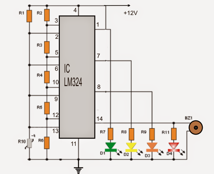
temperarture2Bindicator
BOM for the proposed 4 LED temperature detector circuit
- IC (integrated circuit): LM324
- Thermistor: 1 10K (R10)
- Resistors: 5 5K (R2, R3, R4, R5, R6), 1 10K, 4 220 (R7, R8, R9, R11)
- Diodes LED: 1 green, 1 yellow, 1 red
- 1 "buzzer"
Note: for the thermistor, you have to maintain the terminals long enough, to ensure that it could be terminated across the place where the temperature is in query.

You'll also like:

  • 1.  Simple High Power LED Flashlight Circuit
  • 2.  IC 555 Automatic SOLAR Street Light Circuit: How to Build
  • 3.  IC TL494 PWM Modified Sine Wave Inverter Circuit
  • 4.  4 Step Battery Charging Indicator Circuit
  • 5.  3 LED Battery Monitor Circuit
  • 6.  Simplest Water Level Indicator Circuit using Transistor BC547

About Admin

Hey friends, Thanks a bunch for stopping by this site! I am an engineer with a Bachelor of Engineering in Electronics and Telecommunication. One of my passions is gathering information from all sorts of electronics books and tutorials. I then take that information and compile it into a language that is super easy to understand. My goal is to make those complex electronics circuit concepts and technical terms much more accessible for all the new and budding electronics engineers out there. I can also design customized circuit diagrams as required by the users.
If you have any questions related to this field, please do not hesitate to drop a comment! I am always here and ready to help you out with any queries you might have. I cannot wait to hear from you!

Reader Interactions

Leave a Reply Cancel reply

Your email address will not be published. Required fields are marked *

Primary Sidebar

Categories

  • 3 Phase (4)
  • 8051 Microcontroller (1)
  • Arduino (11)
  • Audio and Amplifier (102)
  • Automation (8)
  • Battery Chargers (64)
  • Bicycle Projects (4)
  • Car and Motorcycle Projects (39)
  • Datasheets (10)
  • DIY Projects (5)
  • Electrical (15)
  • Free Energy (6)
  • Games Projects (2)
  • High Voltage (14)
  • Hobby Projects (30)
  • Household Circuits (2)
  • IC 555 Circuits (5)
  • Ignition Circuits (2)
  • Indicators (50)
  • Infrared (6)
  • Inverter Circuits (29)
  • Lights and Lamps (97)
  • Medical (8)
  • Meter and Tester Circuits (38)
  • Motor Driver (17)
  • New Circuits (56)
  • Oscillators (30)
  • Pets and Pests (5)
  • Power supply (80)
  • Protection Circuits (25)
  • PWM (9)
  • Remote Control (20)
  • Security and Alarm Circuit (48)
  • Sensors and Detectors (66)
  • Signal Processor (23)
  • Solar Controller Circuits (62)
  • SSR (3)
  • Temperature Controller (20)
  • Timer (25)
  • Transformerless (7)
  • Transmitters (12)
  • Tutorials (45)
  • UPS (2)
  • Voltage Regulators (57)
  • Water Sensor and Controller (29)
  • Home
  • Privacy Policy
  • Contact
  • Disclaimer
  • Copyright

© 2025 · Making Easy Circuits