A basic barcode scanner circuit is described down this page article utilizing simply a couple of ordinary components for example an opamp, an LDR and an laser light.
Everyone has observed and are knowledgeable about these types of arrays of thick and thin lines which is often witnessed published on just about all kinds of products, these coded arrangement is often referred to as a bar code. A barcode strip printed on a specific product recognizes various critical information about the product in an encoded type.
Barcode scanners are advanced devices that happen to be employed for scanning bar codes for decoding the concealed tips of the product for the necessary purpose.
Usually these types of devices are comprised of a laser beam which can be thrown across the barcode, the light receives mirrored from the white portions of the barcode on the other hand its assimilated in the black lines of the code.
The above shown differing light intensities are properly grabbed by a photosensor and translated into a varying analogue frequency output.
The above analogue data is consequently transformed into digital pulses by means of a circuit phase and these digital pulses are further transformed into binary form for providing into a PC or a software. The software definitely decodes the facts by knowing the digital/binary design of the given data.
A straightforward homemade barcode scanner is introduced in the following discussion that are available for testing and playing with different barcoded strips and for customizing it as a security key lock device.
Talking about the number of diagrams below, the diagram on the left exhibits a LED/LDR sensor which can be located next to the barcode strip inside a suitable box enclosure for sensing the barcode requirement.
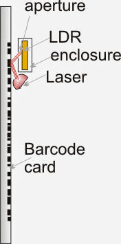
When the barcode card is swiped, the laser beam is incorporated from across the black/white barcode lines with different intensities and is received/detected by the LDR through an properly drilled aperture, as might be visualized in the left diagram above.
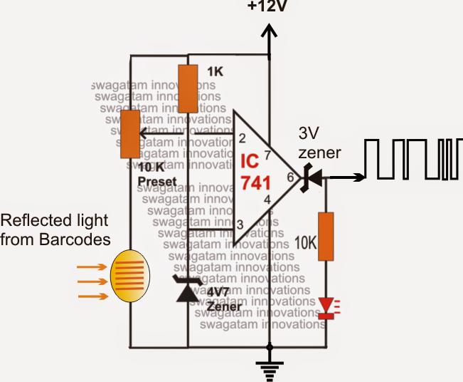
The circuit on the right displays a basic opamp comparator circuit incorporated with the LDR sensor for translating the barcode data into a in the same way varying digital signals
The 10 k preset is gently set such that the opamp has the capacity to reply even to the minutest difference in light felt by the LDR.
Thus the different light intensities from a swiping barcode card is instantly replied by the opamp and is transformed into a in the same way modifying rectangular waveform across its pin6.
Since here we have been merely considering to utilize the decoded data to uniquely activate a appropriate lock and key arrangement, reading only the frequency and the RMS could be adequate for making use of the barcode info as a potential security locking/unlocking data.
Within the next publish we are going to discover ways to create a barcode decoder circuit or signaling a relay mechanism.
Leave a Reply