• Skip to main content
  • Skip to primary sidebar

Making Easy Circuits

Learn and build electronic circuits

You are here: Home / Indicators / How to Make a Morse Code Flasher for Lighthouse Application

How to Make a Morse Code Flasher for Lighthouse Application

Last Updated on February 17, 2018 by Admin Leave a Comment

The submit features a very simple morse code lamp flasher circuit which can be chosen for model lighthouse signalling products.


MORSE2BCODE2BTIMER2BCIRCUIT
Parts list for the morse code lamp for lighthouse application
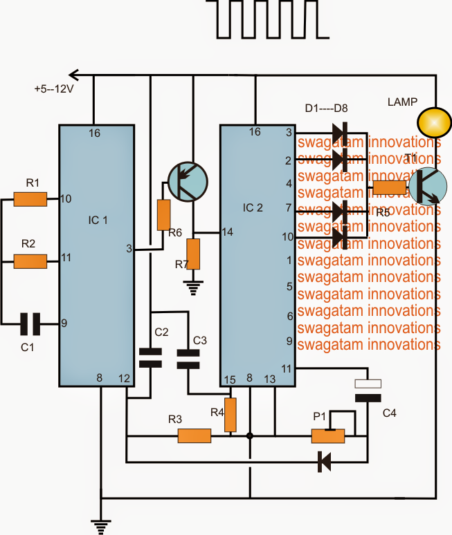
R1 = TO BE CALCULATED
R2, R3, R4, R6, R7 = 1M
R5 = 1K
P1 = 100K PRESET
C1, C2, C3 = 0.22uF
C4 = 10uF/25V
D1---D8 = 1N4148
T1 = 2N2222
T2 = BC557
IC1 = 4060
IC2 = 4017
The projected morse code light house lamp may perhaps be demonstrated in the above diagram. The operation can be conceived with the following points:
IC1 4060 is set as a clock generator at certain predetermined rate by effectively choosing the value of R1. For utilizing the stipulated sequence rate, this certainly will be at the rate of 1/2 seconds at pin3 of the IC
The IC 4017 is wired in its normal sequential decade counter mode where its output pins react with a temporary high with each clock carried out at its pin14.
When the circuit is turned on, capacitors C2, C3 reset the two ICs such that IC1 starts counting from zero and a logic low at its pin3, while IC2 also does the same by keeping its first pin3 high.
With pin3 high at the beginning, T1 is activated which often switches ON the lamp.
After 1/2 second, pin3 of IC2 goes high, switching OFF T2, this generates no impact on pin14 as it gets grounded via R7, pin3 remains to be ON until another 1/2 second.
Throughout the next low from IC1, T2 gets turned on and toggles pin14 of IC2 which causes IC2 to shift its pin3 high to pin2.
Seeing that pin2 is furthermore associated with T1, the lamp happens to be ON for another 1/2 + 1/2 second after which, the sequence is shifted to pin4 of IC2 (not shown). Considering that pin4 is not linked with T1, the lamp has become turned off until another 1/2 + 1/2 second that is for complete 1 second.
Throughout the succeeding next 1/2+1/2+1/2+1/2 periods, the high jumps from the previously listed pinouts to across pin7/10 turning on the lamp one more time for 2 seconds.
As soon as the above valuable time is elapsed, the high is now transferred across pins1,5,6,9,11. Pins1,5,6,9 together implement a delay of 4 seconds, nevertheless since this stage will need to have a delay of 7 seconds according to the request, P1 ought to be modified such that when the high shows up at this pinout, the resetting of IC1 takes place for approximately 3 seconds which plays a role in the total of 7 seconds.
After this the series is flipped back to pin3 of IC2 for repeating the course as per the above stipulated morse code rate.

You'll also like:

  • 1.  Automatic LDR Switch Circuit with Flashing Lamp
  • 2.  Thermal Indicator Circuit for Heatsinks
  • 3.  Mains Wiring Phase, Neutral, Earthing Tester Circuit
  • 4.  Automatic Light Circuit for Washroom  
  • 5.  Coffee Temperature Indicator Circuit
  • 6.  Battery Status Indicator Circuit using two Transistors only

About Admin

Hey friends, Thanks a bunch for stopping by this site! I am an engineer with a Bachelor of Engineering in Electronics and Telecommunication. One of my passions is gathering information from all sorts of electronics books and tutorials. I then take that information and compile it into a language that is super easy to understand. My goal is to make those complex electronics circuit concepts and technical terms much more accessible for all the new and budding electronics engineers out there. I can also design customized circuit diagrams as required by the users.
If you have any questions related to this field, please do not hesitate to drop a comment! I am always here and ready to help you out with any queries you might have. I cannot wait to hear from you!

Reader Interactions

Leave a Reply Cancel reply

Your email address will not be published. Required fields are marked *

Primary Sidebar

Categories

  • 3 Phase (4)
  • 8051 Microcontroller (1)
  • Arduino (11)
  • Audio and Amplifier (102)
  • Automation (8)
  • Battery Chargers (64)
  • Bicycle Projects (4)
  • Car and Motorcycle Projects (39)
  • Datasheets (10)
  • DIY Projects (5)
  • Electrical (15)
  • Free Energy (6)
  • Games Projects (2)
  • High Voltage (14)
  • Hobby Projects (30)
  • Household Circuits (2)
  • IC 555 Circuits (5)
  • Ignition Circuits (2)
  • Indicators (50)
  • Infrared (6)
  • Inverter Circuits (29)
  • Lights and Lamps (97)
  • Medical (8)
  • Meter and Tester Circuits (38)
  • Motor Driver (17)
  • New Circuits (56)
  • Oscillators (30)
  • Pets and Pests (5)
  • Power supply (80)
  • Protection Circuits (25)
  • PWM (9)
  • Remote Control (20)
  • Security and Alarm Circuit (48)
  • Sensors and Detectors (66)
  • Signal Processor (23)
  • Solar Controller Circuits (62)
  • SSR (3)
  • Temperature Controller (20)
  • Timer (25)
  • Transformerless (7)
  • Transmitters (12)
  • Tutorials (45)
  • UPS (2)
  • Voltage Regulators (57)
  • Water Sensor and Controller (29)
  • Home
  • Privacy Policy
  • Contact
  • Disclaimer
  • Copyright

© 2025 · Making Easy Circuits