• Skip to main content
  • Skip to primary sidebar

Making Easy Circuits

Learn and build electronic circuits

You are here: Home / Sensors and Detectors / How to Make a Simple Shadow Detector Circuit

How to Make a Simple Shadow Detector Circuit

Last Updated on November 17, 2024 by Admin Leave a Comment

This shadow detector circuit functions making use of two LDRs and successfully finds the variance between the light levels and generates a loud audible alert siren.
In circuits which utilizes a single LDR (photoresist), the detection might not be as sharp as with two LDRs mentioned right here.
Operational information of the shadow detector circuit might be analyzed given below:
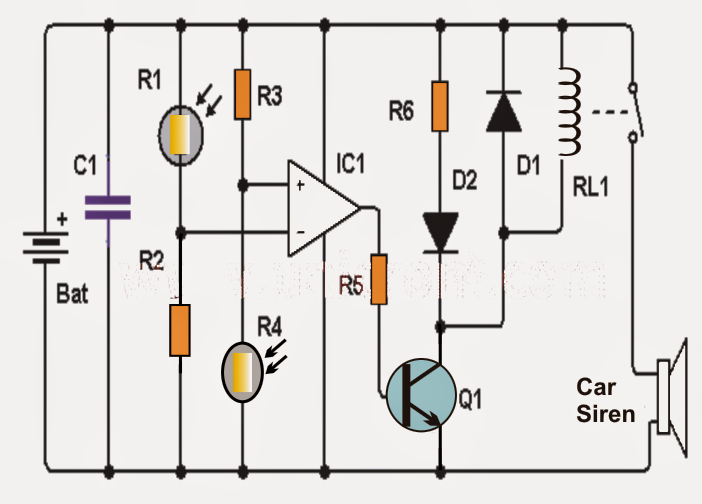
The important elements of this circuit are the two LDRs along with the active functional amplifier, which features as a comparator.
As could be observed in the diagram, the inputs of the opamp are cautiously balanced utilizing alternately located LDRs across the corresponding supply rails together with the specific resistors.
The two resistors might be quite possibly replaced with presets for obtaining a fine adjustment choice and for providing the best possible balance and a suitable zero logic at the output of the opamp.
In standard light circumstances which is without shadow detected (no shade) the two LDRs have the ability to obtain the similar amount of light across the sensing input of the opamp which supplies a low logic level at the output of the IC.
In an event when considered one of the LDRs (for example R1) encounters a shadow or less light than the other (R4), leads to the voltage at the inverting input of opamp to go cheaper than in the non-inverting counterpart, leading to the logic at the output of IC to switch to a high logic.
The above steps triggers transistor Q1, which often triggers the LED and the relay. The LED enables to obtain a visual warning while the relay triggers a siren device.
Essentially you might want to place a semiconductor diode (D1) in identical with the relay, as revealed in the diagram, to guard the transistor Q1 from the relay reverse EMFs.


shadow2Bdetector2Bcircuit
Points to be noted:
- The circuit is driven by 9 volt lead acid battery or any equivalent SMF battery.
- The LDRs ought to be positioned with a separation of about 3cm. for an optimal reply in order to stay away from wrong activating.
Parts list for the offered shadow detector circuit
- 1 Operational amplifier: LM741 (IC1)
- 2 LDRs (photoresistor / LDR) (R1, R2)
- 1 NPN transistor 2N2222 or similar (Q1)
- 1 1N4007 diode (D1)
- 1 red LED diode (D2)
- 9 volt relay (RL1)
- Two 10K resistors (R3 and R4)
- 1 1K resistor (R5)
- 1 resistors 470 (R6)
- 1 100 nF capacitor (C1)

You'll also like:

  • 1.  Touch Operated Flip Flop Relay Switch
  • 2.  Thermostat Circuit for 1KW Room Heater using SCRs
  • 3.  Simple Metal Detector Circuit
  • 4.  How to make a Proximity Detector Circuit Using IC 555
  • 5.  Simple Vibration Detector Circuit
  • 6.  Proximity Detector Circuit – LC Tuned IC CS209

About Admin

Hey friends, Thanks a bunch for stopping by this site! I am an engineer with a Bachelor of Engineering in Electronics and Telecommunication. One of my passions is gathering information from all sorts of electronics books and tutorials. I then take that information and compile it into a language that is super easy to understand. My goal is to make those complex electronics circuit concepts and technical terms much more accessible for all the new and budding electronics engineers out there. I can also design customized circuit diagrams as required by the users.
If you have any questions related to this field, please do not hesitate to drop a comment! I am always here and ready to help you out with any queries you might have. I cannot wait to hear from you!

Reader Interactions

Leave a Reply Cancel reply

Your email address will not be published. Required fields are marked *

Primary Sidebar

Categories

  • 3 Phase (4)
  • 8051 Microcontroller (1)
  • Arduino (11)
  • Audio and Amplifier (102)
  • Automation (8)
  • Battery Chargers (64)
  • Bicycle Projects (4)
  • Car and Motorcycle Projects (39)
  • Datasheets (10)
  • DIY Projects (5)
  • Electrical (15)
  • Free Energy (6)
  • Games Projects (2)
  • High Voltage (14)
  • Hobby Projects (30)
  • Household Circuits (2)
  • IC 555 Circuits (4)
  • Ignition Circuits (2)
  • Indicators (50)
  • Infrared (6)
  • Inverter Circuits (29)
  • Lights and Lamps (97)
  • Medical (8)
  • Meter and Tester Circuits (38)
  • Motor Driver (17)
  • New Circuits (56)
  • Oscillators (30)
  • Pets and Pests (5)
  • Power supply (81)
  • Protection Circuits (25)
  • PWM (8)
  • Remote Control (20)
  • Security and Alarm Circuit (48)
  • Sensors and Detectors (66)
  • Signal Processor (23)
  • Solar Controller Circuits (61)
  • SSR (3)
  • Temperature Controller (20)
  • Timer (25)
  • Transformerless (7)
  • Transmitters (12)
  • Tutorials (45)
  • UPS (2)
  • Voltage Regulators (57)
  • Water Sensor and Controller (29)
  • Home
  • Privacy Policy
  • Contact
  • Disclaimer
  • Copyright

© 2025 · Making Easy Circuits