The article clarifies tips on how to create a very simple sinewave inverter circuit applying PWM feed from an Arduino Uno board, the content also addresses a sinewave 3 phase inverter making use of the same input from an Arduino.
According to the inquiry the first diagram below reveals a single step PWM sine wave inverter employing an Arduino feed for the PWMs.
The design seems quite effortless, the 4047 IC is set up as a totem pole astable for creating the fundamental 50 Hz or 60 Hz frequency.
This frequency forces the two power BJ transistor steps alternately at the stipulated frequency rate.
The transistors could possibly be changed to IGBTs for obtaining better performance, but mosfets needs to be eliminated since these really need specific recognition while developing the PCB, and additional buffer BJT levels to reduce heating up of the mosfets from possible hidden stray inductance or harmonics.
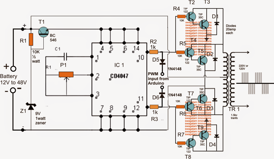
In the above diagram P1 and C1 establish the frequency of the astable which may be changed by suitably creating P1 employing a frequency meter for the planned inverter operating frequency.
T1 as well as the related components which stabilize a limited 9V for the IC 4047 could be removed if the elected inverter operating voltage is not over 15V, on the other hand higher voltage up to 60V may very well be tried out and is suitable for acquiring a stream-lined and a more efficient inverter design.
The PWM from the Arduino is employed across voltage divider networks over the two outputs of the IC via reverse biased diodes which make certain that simply the negative pulses of the PWMs get to know the power stages and slice their conduction correctly.
On account of these PWM cutting up consequence, the brought about current inside the transformer is usually respectively designed for acquiring the designed PWM sinewave stepped up mains voltage at the secondary of the transformer.
The PWM frequency from the Arduino ought to be set at around 200 Hz, if a automated 50 Hz totem pole can be acquired from the Arduino then the IC4047 might be totally discarded as well as the signals could be incorporated directly with R2, R3 left side ends.
3 Phase Inverter circuit making use of Arduino
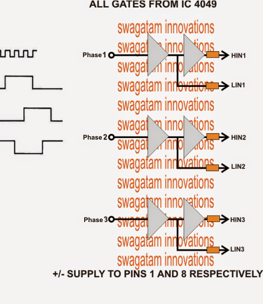
The following two diagram are made to perform as a 3 phase PWM governed inverter from an Arduino.
The first diagram is wired utilizing six NOT gates from the IC 4049. This step is needed for bifurcating the Arduino PWM pulses into complementary high/low logic pairs in order that the a bridge 3 phase inverter driver IC IC IRS2330 can be produced appropriate for the fed PWMs.
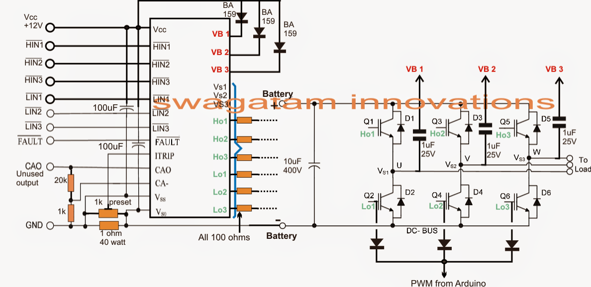
The second diagram from above forms the bridge driver step for the suggested Arduino PWM, 3 phase inverter design, utilizing the IC IRS2330 bridge driver chip.
The inputs of the IC suggested as HIN and LIN embrace the dimensioned Arduino PWMs from the NOT gates and drives the output bridge network established by 6 IGBTs which usually drive the hooked up load across their three outputs.
The 1K preset is employed for handling the over current limit of the inverter by accordingly adjusting it across the shut down pin of the I, the 1 ohm sensing resistor could be diminished correctly if the current a somewhat higher current is described for the inverter.
Leave a Reply