Transcutaneous electrical nerve stimulation (TENS) is a term usually mentioned the utilization of nonpharmacologic or non-invasive type of cure for neutralizing superficial pains.
Studies demonstrate that TENs aids to manage pain both over peripheral as well as central systems.
The central devices incorporate areas of spinal cord and brainstem which are proven to include opioid, serotonin and muscaranic receptors which might be efficiently induced utilizing TENS execution.
Across peripheral areas TENs might help stimulate analgesic influence on receptors for example opioid and alpha2 noradrenergic.
The method entails use of very low DC low frequency pulses by means of electrodes on the patients skin surface for signaling the meant pain control.
The technique can attempted by making use of various frequency ranges from less than 10 Hz up to 50 Hz.
The circuit might be tried out with on a couple of modes the first being in the sensory intensity mode where the patient has the capacity to feel strong results but without motor contraction feeling, along with the second is by way of high intensity mode by which the motor contractions are triggered but with no applicable pain or strong feelings.
Generally the high intensity function is executed by way of a high frequency stimulation while the motor intensity is conducted throughout a comparatively lower frequency electric current.
In spite of this researches have mentioned that the analgesic outcomes could be introduced due to any of the above modes no matter the frequency intensities or variations.
To become more accurate, a low frequency TENs might be accountable for beginning the μ-opioid receptors in the spinal cord and brain stem, although a higher frequency TENs could be utilized to play a role in the activation of δ-opioid receptors around the identical areas.
Additional improvements endorse that the application of TENs may well appropriately reduce pain as a result of the actions of serotoninergic, noradrenergic, muscarinic, and γ-aminobutyric acid (GABA)-ergic systems on the analgesia with the applying of both low or high frequency TENs on a patients skin.

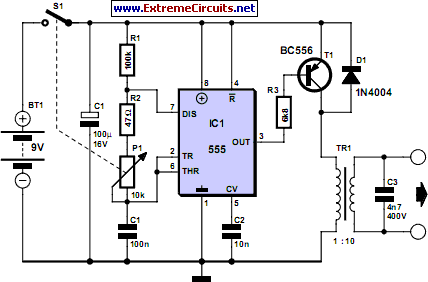
Transcutaneous Electrical Nerve Stimulator (TENS) - schematic
A basic Transcutaneous Nerve Stimulator Circuit could be observed in the above figure, making use of the work horse IC 555 set up in its regular astable mode
P1 is utilized for creating a number of ranges of frequency outputs along with a variations in the pulse widths of the output frequency for the developing the above described TENs methods
T1 is employed for generating TENs at the level of the supply voltage for obtaining highest performance.
The transformer might be any specific normal radio output audio transformer or created by winding 10:100 turns 36 SWG super enameled wire on a small EE ferrite core.
The output of the transformer could possibly be organized in the form tiny protruding copper prods, not too sharp but adequate enough for producing a slight digging effect on the skin and might be wrapped on the impacted area with certain appropriate cohesive band
Leave a Reply