I read an article about a simple car shock alarm circuit. It is a small device that can warn the car owner if their car gets hit or shaken. This could happen because someone is trying to steal the car or due to a hard bump from something outside.
Introduction
Today you will find many cars have security systems that sound an alarm if the car feels a shock or impact. However not all of the cars have these systems, and the ones that do have can be expensive to fix.
This article explained how to make a very cheap car shock sensor alarm. It costs less than 50 cents to make and works pretty well.
How It Works
This alarm uses a simple idea: a microphone detects the impact. The microphone then sends a signal, which is made stronger by a small electronic amplifier.
How the Circuit Works
Looking at the diagram in the article, the circuit has a few important parts:
Microphone Stage:
The microphone is the main part that senses shocks. It’s supported by two small parts:
A 2k7 resistor that helps power the microphone.
A 47uF capacitor that connects the microphone to the rest of the circuit.
Amplifier Stage:
Two small transistors called T1 and T2 make up the amplifier. They make the weak signal from the microphone stronger. A 100K resistor helps keep the amplification stable.
Alarm Activation:
When the microphone picks up a shock, it turns the vibrations into small electrical signals. T1 and T2 amplify these signals to make them strong enough to activate another transistor, T3.
The Siren:
When T3 gets the strong signal, it turns on the alarm siren. This makes a loud sound to warn people nearby that something might be wrong.
A Problem with the Circuit
This alarm is cheap and easy to build, but it has a problem: it can’t tell the difference between real shocks (like a theft attempt) and loud noises (like a door slamming). This might cause false alarms.

Parts List
| Component | Details | Notes |
|---|---|---|
| Spring | Small ballpoint pen spring | Must be highly sensitive and responsive |
| Steel Ball | Small steel ball sourced from a ball-bearing system | Serves as the weight for the pendulum |
| Copper Wires | Used to connect the components as shown in the diagram | Flexible and conductive |
| Key Requirement | The spring should swing or move with even the slightest push or shock | Ensures proper sensitivity |
| Overall Goal | Select the right materials and assemble them to create an effective homemade pendulum sensor |
Pendulum Style Shock Alarm
This alarm system is very useful and can be used in many different ways. It works as a sensor to detect movement and can help protect cars, big objects, houses, or other places where safety is important. By building the circuit, you can create an easy and effective way to guard against problems like theft or damage. It’s also a great tool for trying out simple experiments with technology.
A key part of this system is the relay. The relay is like a switch that can control powerful devices. It can turn on things like loud sirens, horns, flashing lights, and other alarm equipment without any trouble. This makes the system great for situations where you need a strong sound or bright lights to warn people.
Another good thing about this system is that it does not use much power when it is not working. When the relay is off, the circuit uses only a tiny amount of electricity, about 100 microamps. This small power use helps the battery last much longer, so you don’t have to replace it often.
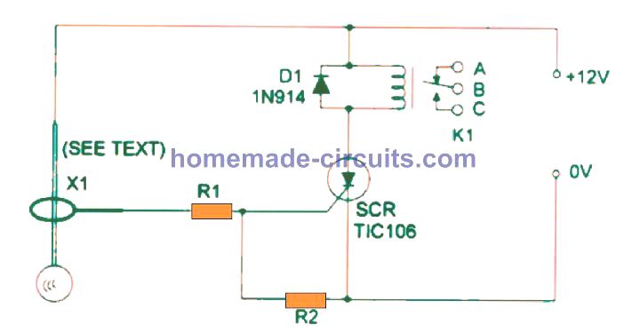
If you want to see how this alarm system works you can look at the diagram in the next figure. The diagram shows how all the parts are connected and how they work together. It makes it easy to understand how the Pendulum Style Shock Alarm operates.

The SCR is at the heart of the circuit and activates the relay when the sensor detects movement.
The voltage of the relay coil is based on the voltage of the power supply.
For lighter loads you can opt for a small DPDT 1A Mini Relay or choose a 10A mini SPDT relay for heavier loads. Typically these relays are rated for 12 VDC and have a maximum consumption of 38 mA.
After being activated the circuit will remain latched indefinitely. To reset the circuit or deactivate the alarm, a simple push of an ON switch can be wired between the SCR's anode and cathode.
The terminals of polarized components such as the SCR and diode must be attentively identified and connected with proper polarity.
Parts List
| Component | Specification/Type | Additional Details |
|---|---|---|
| SCR | TlC106 or SCR | - |
| D1 | 1N914 or 1N4148 | Diode |
| K1 | 12V relay | See text for relay options |
| S1 | SPST toggle switch | Single Pole Single Throw |
| R1 | 22k, 1/4W, 5% resistor | - |
| R2 | 10k, 1/4W, 5% resistor | - |
| X1 | Pendulum sensor | Movement detection sensor |
How to Assemble the Pendulum Shock Sensor Design
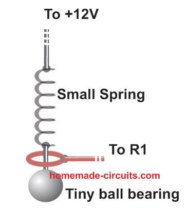
The homemade pendulum sensor that we are going to make includes a few simple parts. We will use a small ballpoint pen spring and a small steel ball, which we can obtain from any ball-bearing system. Additionally, we will need some connecting copper wires, as shown in the figure below.
It is very important for us to choose a spring that is highly sensitive because the spring should start to swing, or move, with even the slightest push or shock. By selecting the right materials and ensuring our spring is very responsive we can create an effective pendulum sensor that works well for our needs.

Leave a Reply